
SLS vs SLM 3D Printing: 5 Critical Differences You Must Know
Both processes spread powder and scan it with a laser. That is where the similarity ends. This page compares SLS vs SLM 3D printing on material state, laser physics, support strategy, dimensional accuracy and cost, so you can pick the right process before you release a drawing.
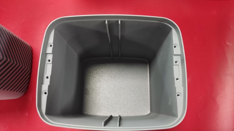
SLS vs SLM 3D printing at a glance
Typical values from production powder bed fusion. Machine, powder and orientation shift these numbers.
| Point | SLS (polymer) | SLM (metal) |
|---|---|---|
| Powder | PA12, PA11, TPU, glass-filled | Ti-6Al-4V, 316L, 17-4PH, AlSi10Mg |
| Bond mechanism | Viscous sintering, particle necks | Full melting into a weld pool |
| As-built porosity | 3–7% by volume | Below 1%, hot isostatic pressing lowers it |
| Support function | Build support only | Anchors the part and drains heat |
| Typical tolerance | ±0.3% with a 0.3 mm floor | ±0.1 mm on small metal parts |
| As-built finish | Ra 8–12 μm | Ra 8–15 μm, worse on downfacing |
| Relative part cost | Lower for small batches | Higher powder, gas and post-processing |
| Best fit | Ducts, housings, fit checks | Load paths, heat, wear surfaces |
Material state: polymer powder versus metal powder
The first split in SLS vs SLM 3D printing is the material itself. SLS handles polymers: PA12, PA11, TPU and filled grades such as glass-filled or carbon-filled nylon. These parts are tough, chemically resistant and fine for housings, ducts, brackets and snap fits. They are not metal, and they do not become metal after any post-process.
SLM handles metal powder. On our side that usually means Ti-6Al-4V, 316L, 17-4PH or AlSi10Mg. The laser melts each layer into a weld pool, so the finished part is a real metal component with a metal's stiffness, thermal conductivity and fatigue behavior.
The expensive mistake is not sending a metal file to a polymer machine. It is using an SLS nylon prototype as a stand-in for a metal part during functional testing. A fit check is fine. A load test at temperature is not. Nylon softens, creeps and fails in a way the metal design never would.
- 1SLS is a polymer processTough, light, chemically stable, non-conductive.
- 2SLM is a metal processReal metal properties, real metal density.
- 3Do not mix them in test plansFit checks yes, load and heat tests no.
Laser physics: sintering versus full melting
In SLS the laser power is deliberately held below the melting point. Polymer particles soften and the surface energy pulls them together, forming necks between grains. The result is a connected structure with microscopic voids. Porosity in an SLS part typically runs 3% to 7% by volume.
That porosity is not cosmetic. It changes how the part behaves under pressure and how it handles moisture. A sealed pneumatic manifold printed in SLS can leak through the walls. If the design needs a pressure boundary, plan on a coating or choose a different process.
In SLM the powder is fully melted. The laser tracks overlap and fuse into dense metal, with porosity normally under 1% and lower again after hot isostatic pressing. The trade is residual stress. Steep thermal gradients build stress into the part, and thin sections can curl or crack during the build.
This is why metal parts get stress relief before they leave the machine, and why support and orientation matter far more in SLM than in SLS.
- 1Sintering leaves 3–7% porosityLeaks and moisture uptake are real risks.
- 2Melting gives near-full densityResidual stress becomes the main concern.
- 3Stress relief is standard for SLMPlan it into the schedule, not after.
Support structures: the self-supporting myth
SLS parts sit in a powder cake. The unsintered powder supports overhangs, so the part needs no anchors and you can nest parts tightly in the build volume. Support removal is a brush, a bead blast and a lot of patience with internal channels.
SLM is different. Metal powder conducts heat away from the melt pool, so supports do two jobs: they hold the part to the plate and they drain heat out of the downfacing surfaces. Remove them too early and the part warps. Design them too thin and the part tears off the plate mid-build.
The practical rule for metal is to keep overhangs above roughly 45 degrees from the build plate, or add support. Internal channels below about Ø1.5 mm are difficult to clear and should be avoided unless you have a proven cleaning route.
With SLS you can break that rule. Channels down to about Ø1 mm can be printed and cleared with compressed air, which is why polymer powder bed fusion is popular for manifolds and ducting.
- 1SLS overhangs need no anchorsPowder cake supports the part.
- 2SLM supports anchor and coolThey are process hardware, not scaffolding.
- 3Keep metal overhangs above 45°Otherwise expect curl and delamination.
Dimensional accuracy and surface roughness
As-built SLS parts usually hold about ±0.3% of the nominal dimension, with a floor around 0.3 mm. Metal parts are tighter, often ±0.1 mm on small features, but they are more sensitive to orientation and to the thermal history of the build.
Surface finish is where both processes lose to machining. As-built SLS lands around Ra 8–12 μm. SLM is similar on upfacing surfaces and noticeably rougher on downfacing surfaces, because that is where the support scars and partially fused powder sit.
If a surface has to seal, slide or mate, abrasive finishing, bead blasting or machining is normal. We machine metal powder bed parts on our 5-axis centers when a bore, a face or a thread has to meet ±0.005 mm.
The deciding question is simple. Does the feature carry a tolerance, a seal or a sliding contact? If yes, budget for secondary machining, in either process.
- 1Polymer: ±0.3% with a 0.3 mm floorFine for housings and fit checks.
- 2Metal: about ±0.1 mm small featuresOrientation still moves the result.
- 3Machined critical featuresBores, faces and threads to ±0.005 mm.
Cost economics and production scale
SLS is cheaper per part at low volume for small parts. No support anchors, high nesting density and inexpensive polymer powder keep the cost curve flat. A hundred nylon brackets can be one build.
SLM costs more for three reasons: metal powder is expensive, the build is slower, and parts need support removal, stress relief and often hot isostatic pressing. Inconel and titanium push that further.
Volume changes the answer. Above a few thousand parts a year, die casting or machining usually wins on unit cost, and we quote all three routes so the comparison is honest. Between one and a few hundred parts with metal properties, SLM is often the only sensible path.
For prototypes that need to look and feel like a production part, vacuum casting from a machined master is a common middle option. It is a mold, not a powder bed, but it beats both processes on cost at 20 to 50 units.
- 1SLS wins small polymer batchesCheap powder, tight nesting, no anchors.
- 2SLM carries post-processing costSupport removal, stress relief, HIP.
- 3Above a few thousand partsDie casting or CNC usually wins.
Which process to pick
Choose SLS when the part is polymer, non-structural, and you want low cost per unit with complex internal channels. Choose SLM when the part carries load, sees heat or wear, or must be metal for a regulatory or functional reason. If the geometry has a sealing face, a bore or a thread, add machining to either route.
SLS vs SLM 3D printing: common questions
Is DMLS the same as SLM?
Functionally, yes. DMLS and SLM both melt metal powder in a powder bed with a laser. The names come from different machine vendors and marketing departments, not from different physics.
When a supplier quotes DMLS, ask for the alloy, the density, the build orientation and the post-processing. Those four answers tell you more than the acronym.
Can SLS print metal parts?
No. SLS consolidates polymer powder below its melting point. Metal powder needs full melting, which is SLM or electron beam melting.
Some binder jetting processes use metal powder and a polymer binder, then sinter the part in a furnace. That is a different route with its own shrinkage allowance, and it should not be quoted as SLS.
How much machining do printed parts need?
It depends on the feature, not the process. Cosmetic surfaces can stay as-built. Sealing faces, bearing bores, threads and mating faces usually get machined.
On our 5-axis centers we hold ±0.005 mm and Ra 0.8–1.6 μm on those features. Send the print file and the drawing together so the machining stock is planned before the build.
Which process gives a better surface finish?
As-built, neither is smooth. SLS sits around Ra 8–12 μm. SLM is similar on upfacing surfaces and rougher on downfacing ones.
Bead blasting, tumbling or polishing improves both. If the finish requirement is below Ra 1.6 μm, plan on machining the surface rather than finishing the print.
How do I decide between printing and CNC machining?
Use printing for geometry that is hard to cut: internal channels, lattice, organic brackets, low volume. Use CNC when the part is a prismatic shape with tight tolerances, when you need a specific alloy, or when the volume justifies tooling and fixtures.
For many projects the answer is both: print or cast the blank, then machine the critical features.
Send us the model and the drawing
We quote machining and additive routes side by side, with a free DFM analysis inside 12 hours.
12-hour quoteDFM analysis includedNDA on request
More process notes
We publish setup notes, tooling trials and inspection data from the factory floor.











