
01
Flank wear shows up early
A spline cut with the wrong pressure angle or too little backlash loads one flank harder than the other. Fretting appears at the contact ends first, then the teeth spall. Rework means a new shaft, not a touch-up.
We cut internal and external splines on shafts and gears by hobbing, shaping, broaching and 5-axis milling. Torque goes through the flanks, not a keyway, so the shaft keeps its section and its balance at speed.
Most spline problems trace back to one of four habits.
A spline cut with the wrong pressure angle or too little backlash loads one flank harder than the other. Fretting appears at the contact ends first, then the teeth spall. Rework means a new shaft, not a touch-up.
If the spline pitch diameter is not concentric with the bearing journals, the mating gear rocks once per revolution. You get noise at speed and a wear pattern that moves around the tooth.
Too much backlash lets the shaft rock each time torque reverses. That impact loads the tooth corners, and the corners are where cracking starts. Tight backlash with the wrong fit is just as bad: the joint seizes and the flanks gall.
When both members are case hardened to the same depth, they wear each other. One side should be softer, or the pair should be nitrided to a controlled case. Getting this wrong means replacing both parts, not one.
Four profiles cover most work. The choice is a load, alignment and cost decision.

Parallel side splines are simple and cheap to cut. The flanks stay parallel in both the radial and axial directions, so they slide freely and take misalignment well. They suit sliding joints and low-speed couplings, but the sharp corners at the root concentrate stress.
Involute splines use the same curve as a gear tooth, just shorter. The curve spreads stress over the flank instead of piling it at a corner, so a given shaft carries more torque or lasts longer at the same torque. When the two halves will run slightly out of line, we crown the male teeth so contact stays near the middle of the flank.
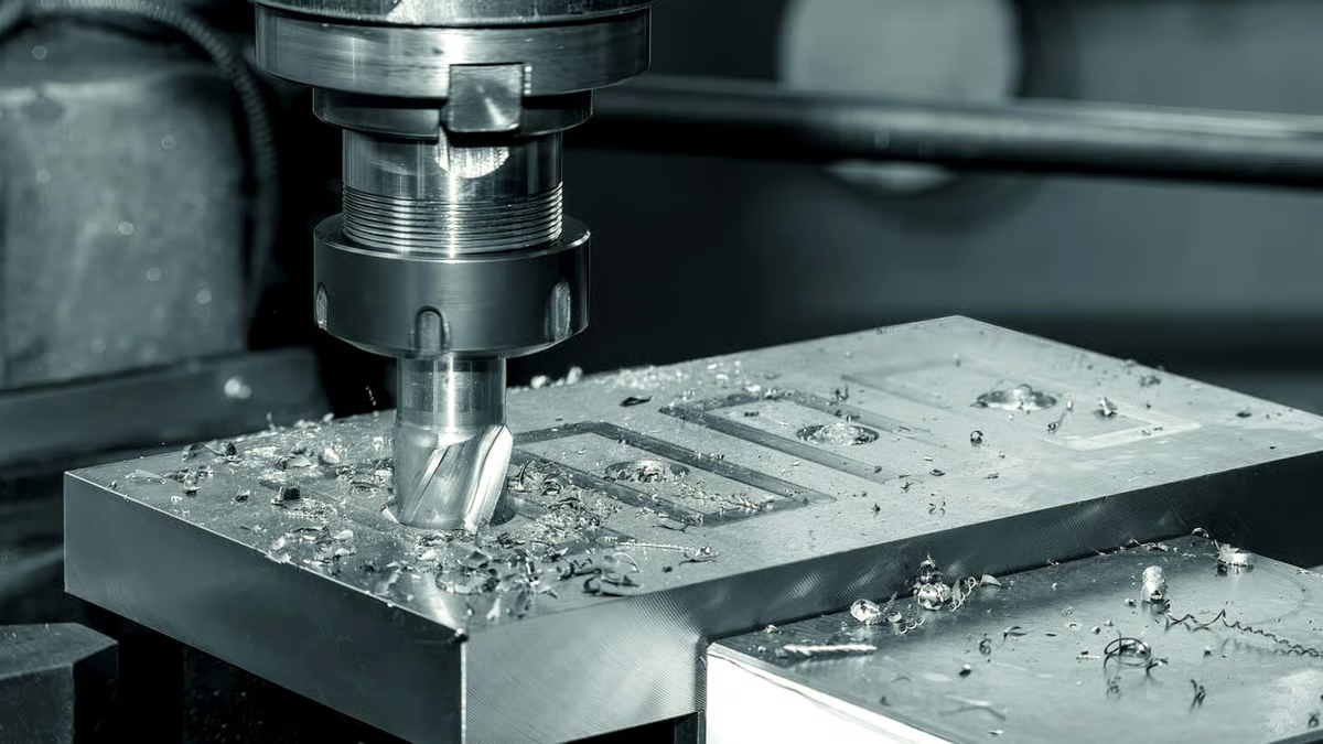
A spline is only as good as the datum it is cut from. We turn the bearing journals, the spline pitch diameter and the locating faces in one setup wherever the part allows, so the spline runs true to the journals that actually carry the shaft.
For external splines we hob or mill on a 4-axis or 5-axis center, then check the profile on the machine. Internal splines are shaped or broached, and blind or interrupted bores go on the mill with a small cutter. Long shafts up to 4,000 mm are supported on the Ø400 mm rotary table to keep the cut stable away from the chuck.
Use this as a first filter before the drawing goes out for quote.
| Spline type | Best for | Watch out for |
|---|---|---|
| Parallel side (straight) | Sliding joints, low speed, low cost | Root corner stress, no self-centering |
| Involute 30° | High torque, fatigue-loaded shafts | Needs matched cutting tools, less slide |
| Involute 45° | High torque with tighter fit | Higher cutting load, tooling cost |
| Crowned involute | Misalignment, flexible mounts | Only handles a few degrees of angle |
| Serrations | Small-diameter shafts | Low torque per tooth, shallow flanks |
One shop for the profile, the gear and the finishing.
Hobbing and milling of parallel, involute and crowned profiles on shafts from Ø6 mm to Ø400 mm, with runout held against the bearing journals.
Shaping, broaching and milled internal profiles in hubs, gears and couplings. Blind and interrupted bores are cut on 5-axis centers.
Matched male and female members cut to the same module and pressure angle, with backlash set to your assembly, not to a generic default.
Shaft bodies, journals, shoulders and keyways turned and milled in the same program as the spline, so datums stay consistent.
Case hardening, nitriding, black oxide, plating and anodizing. We grind after heat treat when the spline needs to hold tolerance.
Profile, pitch diameter, runout and backlash measured and recorded. Reports supplied on request with the shipment.
Numbers we can hold on a production run.
| Item | Range | Notes |
|---|---|---|
| Shaft diameter | Ø6 mm to Ø400 mm | Larger on request |
| Maximum length | Up to 4,000 mm | Rotary table support |
| Tolerance | ±0.005 mm | On critical diameters |
| Surface finish | Ra 0.2–3.2 μm | Depends on profile and material |
| Materials | Steel, stainless, alloy, titanium | 1018, 4140, 4340, 17-4PH, TC4 |
| Order size | 1 to 10,000+ parts | No minimum order quantity |
Fifteen years of turning and milling, mostly on parts that rotate.
Founded in 2011. Most of our work is shafts, gears, housings and fixtures where concentricity decides whether the assembly works.
Not a lab number. Critical diameters and spline pitch diameters are held at ±0.005 mm on the machines that cut them.
Sixteen 5-axis machines and sixteen mill-turn centers cut splines, pockets and ports without moving the part between setups.
Send a drawing and get a quotation with a manufacturability read inside 12 hours. Production can start within 24 hours of approval.
ISO 9001:2015, IATF 16949:2016, ISO 13485:2016 and ISO 27001:2022. Raw material check, in-process monitoring and final inspection are standard.
Uploads are secure, and we sign an NDA on request. Your print does not get passed to another shop for comparison.
Splines on motor shafts and gearbox inputs must hold balance at high rpm and survive torque reversal. We hold pitch diameter concentric to the journals and set backlash per assembly.

Shaft profiles for actuators and control linkages need material traceability and a clean flank with no sharp root corner. Involute profiles with controlled case depth cover most of it.

Long drive shafts up to 4,000 mm are common here. Support on the rotary table keeps the spline cut true along the full length instead of tapering near the end.
Small splined shafts in harmonic and planetary joints need tight runout and repeatable fits across a batch. We measure profile and runout on every part, not a sample.
Use a spline when the torque is high, the load reverses, or the shaft must slide while transmitting torque. A keyway cuts a slot into the shaft and weakens the section at exactly the point where bending stress peaks.
A spline spreads the load over several teeth and keeps the shaft section more uniform. The trade-off is cost: cutting a spline takes longer and needs a matched internal member.
Start with the load path. If the joint slides and the speed is low, parallel side splines are the cheapest answer. If the shaft is fatigue loaded and carries high torque, go involute.
If the two members will run a few degrees out of line, crown the male teeth. For small-diameter shafts with light torque, serrations are enough.
We cut the spline from the same datum as the bearing journals wherever the part geometry allows. That means one setup for the diameters that actually locate the shaft in the assembly.
After cutting, we check pitch diameter runout and total indicated runout against those journals and record the numbers.
Yes. A broach needs a through path, so blind or interrupted bores are milled on a 5-axis center with a small cutter instead. The profile is generated by the tool path, not by a push broach.
Depth and corner radius decide whether milling is practical. Very deep blind bores in hard material are the case where we will tell you to redesign.
Backlash depends on how the joint is used. A fixed coupling wants the minimum clearance that still assembles. A sliding joint under misalignment needs more, or the flanks gall.
Tell us the application and we will set the fit. If you already have a backlash range from the assembly drawing, we cut to that.
When the spline has to hold ±0.005 mm after case hardening or nitriding, yes. Heat treat moves the part, and the distortion is not predictable enough to leave in the cut.
For looser fits we cut to size and heat treat after, which is cheaper and faster.
A 2D drawing with the spline callout is best: profile type, module or diametral pitch, number of teeth, pressure angle and fit class. A 3D model helps for the shaft body.
If you only have a sample part, send photos with the key dimensions and we will work from that. Quote and DFM feedback come back within 12 hours.
Uploads are secure and confidential. We sign an NDA on request before drawings are shared, and your files are not passed to other shops.
If you would rather not send a full print at first, send the spline callout and overall envelope and we can give a budgetary read.
Upload a print or a 3D model and get a quotation with manufacturability feedback within 12 hours. One prototype or ten thousand, no minimum order quantity.
12-hour quote100% inspectionNo minimum orderNDA on request
Trusted by engineers and manufacturers worldwide










Upload your 3D model or 2D drawing and get a quotation with a free DFM analysis. Maximum processing size 4,000 mm.
CNC Metals 13 grades
CNC Plastics 10 grades
Machines & processes 12 options
Surface & post-processing 10 options
Material: not selected Machine: not selected Post-process: not selected
Fill in this short form and we'll open WhatsApp with your message ready to send. We only use these details to reply to you.
Nothing is sent until you press send inside WhatsApp.