
The rise of rapid prototyping, explained for engineers
This page covers how the rise of rapid prototyping changed the way mechanical parts move from CAD to a tested assembly. It is written for design engineers and sourcing engineers who need to pick a process, not a slogan. After reading it you should be able to say which parts belong on a CNC prototype run and which belong on a printed or cast one.
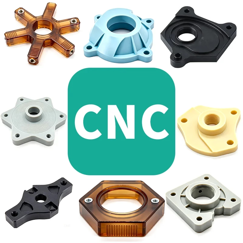
What actually drove the rise of rapid prototyping
The rise of rapid prototyping did not come from one machine. It came from three changes arriving within a few years of each other. Parametric CAD made it cheap to revise a model. Toolpath software made it possible to cut a curved surface without a drawing full of coordinates. And the demand for shorter product cycles pushed buyers to order one part instead of a thousand.
The older path was rigid. A design went to a pattern shop, then to a foundry or a die shop, then to a machining cell. Each handoff added weeks and locked in geometry. A change after the mold was cut was expensive, so teams avoided changes. They froze bad decisions and shipped them.
Rapid prototyping broke that sequence. A prototype is now cut or printed from the same CAD file the production part will use. The file is the artifact. The process is a detail you choose later.
Where CNC machining fits in rapid prototyping
Subtractive prototyping starts with a solid billet and removes material until the geometry matches the model. That matters because the result is the same class of object as the production part: same alloy, same grain direction, same surface. If you need to know whether a 7075 bracket survives a load cell test, a machined prototype answers that question. A printed one does not.
On a 5-axis machine, a part with compound angles can often be cut in one setup. That removes the stacked tolerance error you get when a part is repositioned four times on a 3-axis mill. For prototypes that must mate with an existing assembly, setup count is often the difference between a part that fits and a part that needs rework.
CNC also covers size ranges that printing does not handle well. We run a 4,000 mm maximum processing size, with common travels of 750 × 1,150 × 550 mm and 600 × 600 × 600 mm, down to compact 500 × 500 × 450 mm and 500 × 310 × 200 mm envelopes. A Ø400 mm rotary table handles round parts in the same setup.
The tradeoff is cost per part at low quantity. Cutting a prototype from solid takes machine time, so a 20 mm cube with a simple bore costs more than the same shape from a printer. That gap closes as geometry gets harder.
Where 3D printing still wins
Additive processes build up material instead of cutting it away. Internal channels, lattice fill, and cavities that a cutter cannot reach are all possible. If the open question is whether the harness reaches the connector, a print answers it in a day and a machined part may not be able to answer it at all.
Printing also suits early form checks. A housing that will eventually be die cast can be printed in resin or nylon to check grip, clearance, and how it sits in a hand. Nobody measures it with a micrometer. It is a shape question, and shape is cheap to test.
The limits show up in mechanical claims. Layer direction changes strength. Surface finish as-built is rough compared to machined faces. Tolerances are looser, and holes usually need drilling after printing if they carry a fastener.
A useful rule: print to test shape and fit, machine to test function and strength. Most programs use both, in that order.
Tolerance, material, and size limits you should expect
Machined prototypes from our shop hold ±0.005 mm (±0.0002 in) on features that need it. Not every feature needs it. Aesthetic surfaces, clearance holes, and non-critical pockets can run looser, and letting them run looser keeps the price down. Tell the shop which dimensions actually matter and which are reference.
Surface finish follows the same logic. Ra 0.2–0.8 μm is a fine finish for sealing faces and bearing bores. Ra 0.8–1.6 μm covers most mating surfaces. Ra 1.6–3.2 μm is as-machined and fine for brackets. Specifying a fine finish across a whole part adds time for no functional gain.
Material choice in prototyping is wide. Aluminum grades run from 6061 and 6061-T6 through 2024, 5052, 5083, 6063, 6082, 7075 and ADC12. Stainless covers 303, 304, 316, 316L, 420, 430, 431, 440C and 17-4PH. Steels include 1018, 1045, 4130, 4140, 4340, A36 and tool steel. Copper and brass, titanium, Inconel, magnesium and engineering plastics such as POM, PEEK and carbon fiber are also available.
Size is the other boundary. Parts beyond roughly 4,000 mm, or features smaller than the cutter that must reach them, need a different plan. Deep narrow slots and sharp internal corners are the usual blockers. A corner radius at least equal to the cutter radius avoids a second operation.
How a prototype loop actually runs
The loop starts with a CAD file and a statement of what the part must prove. That statement is the most useful thing you can send. A prototype that tests fit needs different tolerances than one that tests fatigue life.
From there a DFM review flags thin walls, unreachable features, and dimensions that will be hard to hold. We return quotation and free DFM analysis within 12 hours, and production can start within 24 hours. Parts typically ship in 3–5 days.
Inspection closes the loop. We inspect 100% before shipment, with raw material check, in-process monitoring and final inspection, and reports on request. A CMM report on the critical dimensions tells you whether the next revision should change the design or the tolerance.
Then you iterate. The point of the rise of rapid prototyping is not speed for its own sake. It is that you can afford to be wrong early, when being wrong is cheap.
Choosing between CNC and additive for a prototype
Match the process to the question the prototype has to answer.
| Question the prototype answers | CNC machining | 3D printing |
|---|---|---|
| Does the part fit the assembly? | Yes, with production-grade tolerance | Yes, if holes are reamed after printing |
| Will it survive a load test? | Yes, same alloy and grain as production | Only for rough ranking, layer lines weaken it |
| Are there internal channels? | Limited by cutter reach | Yes, complex channels are routine |
| Is surface finish critical? | Ra 0.2–1.6 μm available | Rough as-built, needs post-processing |
| How fast is the first part? | Quote in 12 hours, ship in 3–5 days | Often faster for small simple shapes |
| Cost at quantity 1 | Higher, machine time dominates | Lower for small parts |
| Cost at quantity 10,000 | Drops sharply, no tooling | Not competitive |
The short version
If the prototype has to prove strength, fit or surface function, machine it. If it only has to prove shape, print it. When both matter, print first and machine the revision.
Common questions
How many prototypes can I order before committing to production?
There is no minimum order quantity. We run from one prototype to 10,000+ part runs, so you can order a single piece to validate a design and then scale the same geometry into a larger batch.
The process does not change between one part and a thousand. Tooling is not required for CNC, so nothing is thrown away when the design changes.
Can a machined prototype use the same material as the production part?
Yes, and it usually should. Aluminum, stainless, steel, copper, brass, titanium, Inconel, magnesium and engineering plastics are all stocked for prototyping work.
Using the production alloy means the test result transfers. A prototype in a substitute material only tells you about the substitute.
What tolerances are realistic on a first prototype?
We hold ±0.005 mm (±0.0002 in) on critical features. That is achievable on a first article, but it costs machine time.
A practical approach is to mark only the dimensions that affect function as tight, and leave the rest at general machining tolerance.
How do you protect the design during a prototype run?
Uploads are secure and confidential. An NDA is available on request before any file is reviewed.
The four certifications we hold, ISO 9001:2015, IATF 16949:2016, ISO 13485:2016 and ISO 27001:2022, cover quality and information security.
Can prototypes be finished like production parts?
Yes. Anodizing in clear, color, hardcoat and conductive variants, electroless nickel, zinc, silver and gold plating, powder coating, black oxide, bead blasting, tumbling, brushing and polishing are all available.
Laser marking and engraving can be added with a minimum character height of 1.5 mm.
What file format and information do you need for a quote?
A STEP or native CAD file plus a drawing for any dimension that is critical. If the part is a form check, say so and the tight dimensions can be left off.
The most common delay is an unclear critical dimension. One line of text about what the part must do removes it.
Send a CAD file and get a machining plan
Quotation and free DFM analysis within 12 hours, with production able to start in 24 hours and 100% inspection before shipment.
12-hour quote100% inspectionNo minimum order quantity
More from the shop floor
We publish setup notes, tooling trials and inspection data from the factory floor.











