
Turning PEEK Engineering Plastics: Heat, Tools and Tolerance Control
PEEK machines like a metal that will not carry heat away from the cut. This page explains how that one fact sets tool choice, speed, feed and inspection, and how to judge when turning suits a part and when it does not.
In this article
- 1
- 2
- 3
- 4
- 5
- 6
Why Turning PEEK Engineering Plastics Is a Heat Problem
PEEK turns cleanly on a lathe. The trouble is where the heat goes. In aluminum, most cutting heat leaves with the chip and the rest spreads into the part and tool. PEEK keeps it at the cutting edge. The chip comes off hot, the insert stays hot, and the machined surface stays soft long enough to smear.
The number to remember is the glass transition temperature, near 143 °C. Below it the material shears cleanly and the chip breaks. Above it the same cut starts to push material instead of cutting it. You get torn surfaces, burrs that fold rather than snap, and dimensions that move after the part cools.
Thermal conductivity explains the rest. Unfilled PEEK sits around 0.25 W/m·K, roughly a thousandth of aluminum. Heat has nowhere to go except into the insert and a thin skin of the part. That skin is the surface you are trying to hold a tolerance on, so the surface is the first thing to suffer.
One consequence surprises people who come from metal work: a light finishing pass can be hotter than a heavy roughing pass. Rubbing generates more heat than shearing. If the insert is below the nose radius engagement, the tool rubs, and the finish gets worse as you take less material.
Carbide Grades and Geometry That Survive the Cut
Use uncoated or lightly coated micro-grain carbide. Aluminum oxide and titanium nitride coatings are hard, but they hold heat at the edge and they do not slide on PEEK the way they slide on steel. A sharp polished uncoated insert usually outlasts a coated one on this material.
Geometry matters more than grade. A positive rake, usually 10° to 15°, lowers cutting force. A small nose radius reduces the contact patch and the heat it generates. Inserts sold for aluminum finishing, with a polished top face and a sharp edge, are close to ideal for unfilled PEEK.
Do not reuse an insert that has already run steel or aluminum. A worn edge rubs, and rubbing is what melts PEEK. Change tools on schedule, not on failure. On long runs we log tool changes by part count and check the surface with a comparator before the finish drifts.
For carbon fiber filled grades the rules shift. Abrasive fiber wears the edge fast, so expect shorter tool life and plan for it. Polycrystalline diamond inserts cost more per edge but hold size far longer on CF30 and similar compounds. On a 500-part run the PCD edge usually wins on total cost.
Speeds, Feeds and Depth of Cut in Practice
Start conservative and read the chip. For unfilled PEEK, a surface speed of 150 to 250 m/min with a feed of 0.05 to 0.15 mm/rev is a workable window on a rigid lathe. Take depth of cut of 0.5 to 2.0 mm on roughing so the edge shears instead of rubs.
If the chip comes off as a continuous string that whips, you are cutting too hot or too slow on feed. Increase feed per revolution. If the chip is powder, you are rubbing. Increase depth of cut or change the insert. Stringy chips on a finishing pass usually mean the feed is below the nose radius.
Carbon filled grades want less speed and more feed. Drop surface speed to roughly 100 to 150 m/min and keep the feed up so the fiber is cut, not pulled. Pulled fiber leaves a fuzzy surface and a dimension that creeps as the fiber springs back.
Coolant is a choice, not a default. Flood coolant helps carry heat away on deep bores and long parts. Air blast alone works well on short, stiff parts and avoids the moisture uptake that PEEK can show over time. Whichever you pick, be consistent, because the thermal state sets the final size.
Rough, then let the part rest. A PEEK turning that measures on size while warm will measure small after it cools. On tight work we rough, wait, then take a light finishing pass. That rest period is often the difference between holding ±0.005 mm and chasing it all afternoon.
Chip Control, Burrs and Surface Finish
PEEK does not break chips the way brass does. You manage the chip with feed, depth and geometry rather than with a chipbreaker. A string that clears the tool and falls away is fine. A string that wraps the workpiece is a sign to change feed or insert.
Burrs on PEEK form as thin, tough fringes at the part edge. They do not snap off. A sharp positive insert and a light chamfer pass remove most of them. For sealing faces, plan a finishing pass that cuts toward the supported end so the edge does not lift.
Surface finish is mostly a heat story. A cool, sharp cut on unfilled PEEK reaches Ra 0.8–1.6 μm without extra work, and Ra 0.2–0.8 μm is achievable on facing and outside diameters with a fine feed and a fresh edge. Chasing the same finish on a dull insert only raises the temperature.
Carbon filled PEEK sits coarser, typically Ra 1.6–3.2 μm as machined, because the fiber ends stand proud of the resin. That is normal and usually acceptable. If a sealing surface needs better, say so at quoting so the process can include a dedicated finishing pass.
Part Features That Turn Well and Features That Do Not
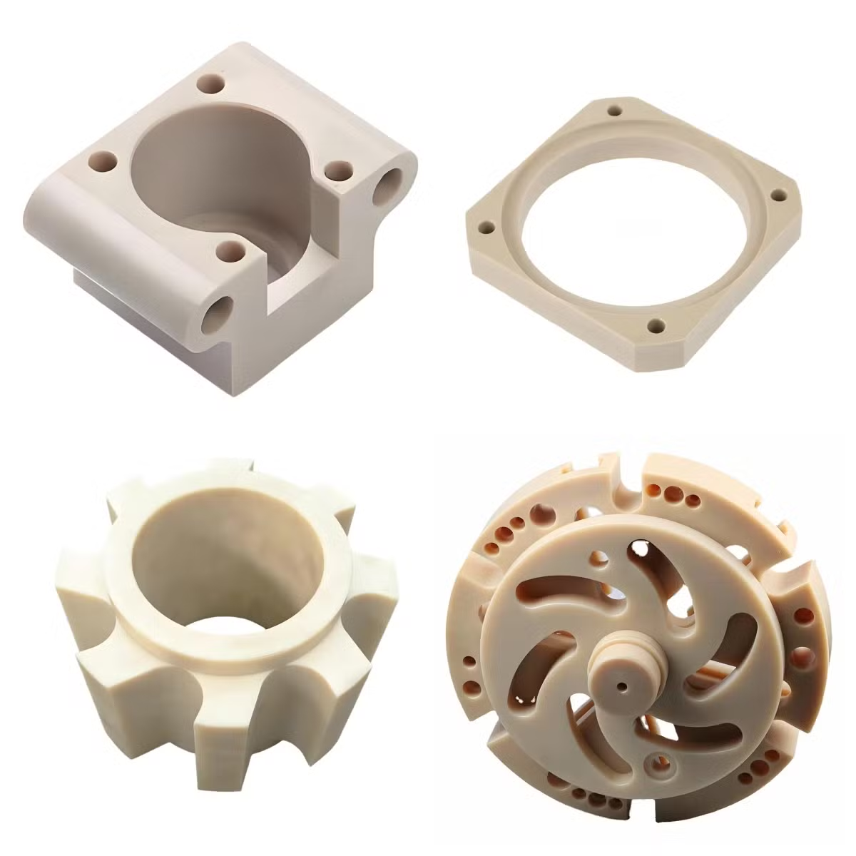
Turning suits round, axially symmetric parts: bushings, seal rings, valve seats, insulators, wear pads, support and locating pins. PEEK's wear resistance and low friction make those parts last where a metal would gall or corrode.
Thin walls are the common failure. PEEK has a high thermal expansion for a plastic and low stiffness, so a 1 mm wall on a Ø60 mm tube will move during and after the cut. Keep wall thickness above roughly 2 mm where you can, and support the part with a mandrel or tailstock on long bores.
Long slender parts deflect. If the length to diameter ratio passes about 4:1, plan for a travelling steady or a support. Otherwise the tool pushes the workpiece away, the cut goes quiet, and the diameter drifts along the length.
Cross holes, slots and flats need a second operation. A mill-turn center handles them in one setup, which matters when a cross hole has to line up with a turned bore. Trying to hold that relationship across two setups adds error for no gain.
Grade and Process Selection for Turned PEEK Parts
Judging which stock and which process fits the part.
| Grade or case | Turning behavior | Typical use | When to avoid |
|---|---|---|---|
| Unfilled PEEK | Cuts clean, best finish, tool life long | Seal rings, insulators, bushings | High load with abrasive contact |
| 30% carbon fiber | Abrasive, needs PCD, coarser finish | Wear pads, support and locating parts | Cosmetic or sealing surfaces |
| 30% glass fiber | Abrasive, moderate strength gain | Structural brackets, spacers | Tight tolerance on thin walls |
| PEEK with PTFE or graphite | Softer, smears easily, watch heat | Low friction bearings, seals | Sharp edges and fine threads |
| Mill-turn in one setup | Holds cross-hole to bore position | Parts with cross holes or flats | Simple round parts, no advantage |
When Turning PEEK Is the Right Call
Use turning for round, axially symmetric parts in unfilled PEEK where a clean Ra 0.8–1.6 μm finish and ±0.005 mm on diameter matter. Switch to carbon filled grades only when wear resistance is the driver, and accept a coarser finish and PCD tooling. If the part is mostly prismatic with deep pockets, milling or a mill-turn setup beats a pure turning process.
Turning PEEK: Common Questions
Can you hold ±0.005 mm on turned PEEK?
Yes, on diameters and faces where the part is stiff enough to resist cutting force and thermal growth. The tolerance is set by the machine and the process, not the material.
It gets harder on thin walls, long bores and carbon filled grades. There, we rough, let the part settle, then finish, and we tell you up front which dimensions we can guarantee and which we cannot.
Why does my PEEK part measure small after it cools?
PEEK expands more with heat than metal does. If you measure the part warm, right off the lathe, you are measuring the expanded size. It shrinks as it cools.
The fix is a controlled rest before the finishing pass and a final check at room temperature. On tight work we hold parts in a temperature-stable area before inspection.
Is coolant required when turning PEEK?
No. Flood coolant helps on deep bores and long parts, and air blast is enough on short, stiff parts. PEEK can take up moisture over time, so some shops prefer air.
What matters more is consistency. Changing from flood to air mid-run changes the thermal state and the final size. Pick one method for the batch.
Do I need PCD tooling for carbon filled PEEK?
For short runs, no. Micro-grain carbide works, you just change edges more often. For long runs on CF30 and similar grades, PCD usually wins on cost per part.
The abrasive fiber dulls the edge quickly, and a dull edge rubs. Rubbing is what ruins the finish and the size on filled grades.
What wall thickness is safe on a turned PEEK tube?
Aim for 2 mm or more where the design allows. Below that, cutting force and thermal growth both push the wall around and the roundness drifts.
If a thinner wall is required, we support the bore with a mandrel and take light finishing passes. Expect a longer cycle and a higher cost, and we will say so at quoting.
Can turned and milled features be done in one setup?
Yes, on our mill-turn centers. That keeps a cross hole, flat or slot in the same relationship to the turned bore as the drawing shows.
For a part that is only round, a lathe alone is faster. The mill-turn setup earns its cost when the feature relationship is tight.
Quote Your Turned PEEK Part
Send the drawing and we return a quotation with a free DFM analysis within 12 hours. Uploads stay confidential, and an NDA is available on request.
12-hour quote100% inspectionNo minimum order quantity
More Machining Notes
We publish setup notes, tooling trials and inspection data from the factory floor.











