
What Are Free Edges in a CNC Machine Part?
Free edges are the outer boundaries left after the cutter removes material. They are not mating surfaces, bores, or threads, yet they decide how a part handles, coats, and assembles. This page explains how free edges in a CNC machine part form, when a sharp one is a defect, and how to call them out on a drawing.
In this article
- 1
- 2
- 3
- 4
- 5
- 6
Where free edges in a CNC machine part sit
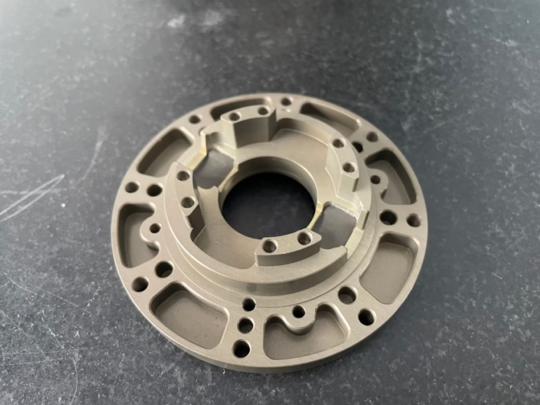
A free edge is any external corner or periphery of a part that is not a functional mating face, an internal bore, or a threaded section. Free edges in a CNC machine part are the outer boundary of the workpiece after stock has been cut away. On a plain aluminum bracket, every outside corner and the rim of every through hole counts as one.
The term is useful because it separates two very different requirements. A bearing seat or a dowel hole has a tight size and position tolerance. A free edge usually has no dimensional function at all. Its job is to be safe, coatable, and stable. That is why drawings often control free edges in a CNC machine part with a note instead of a tolerance.
Material is sheared or milled away at these boundaries. The cutter leaves a burr on one side and a slightly rolled-over lip on the other. On 6061-T6 aluminum the burr is soft and easy to remove. On 316L stainless or Ti-6Al-4V it work-hardens at the tip and can lift a sliver of material when a dull tool passes.
Sharp is not the same as wrong. A stamped shim or a shear-cut plate can run with a raw edge. The moment a free edge touches a person, a gasket, a wire, or a coating line, it becomes a controlled feature and needs a callout on the print.
How a cutter creates a free edge, and what it leaves behind
Every milling pass ends with tool exit. As the flute leaves the work, the remaining material has no support on one side, so it bends instead of shearing cleanly. That bend is the burr. Its size depends on feed per tooth, tool sharpness, and how much material is left under the edge.
A 12 mm carbide end mill at 0.08 mm per tooth in 6061 will leave a burr under 0.05 mm on the top face. Push the same tool into 304 stainless at the same chip load and the burr grows, because the material work-hardens faster than the tool can cut it. Reduce chip load and increase speed instead.
Drilling leaves a different signature. At breakthrough, the margin of the drill pushes a cap of material out of the exit side. On a through hole in 1018 steel, that cap is a sharp ring. Support the exit face with a backing plate, or drill to within 0.5 mm and finish with a smaller pilot.
Heat changes the picture too. Cutting at Ra 0.8–1.6 μm with a light finish pass gives a cleaner edge than a heavy roughing pass, because the final pass removes the damaged layer the roughing pass created.
Why an untreated free edge causes trouble downstream
A raw edge is a handling hazard first. Technicians wear gloves, but a 0.1 mm wire edge on a bracket still cuts through nitrile. In medical and food-contact work, a burr is also a trap for residue that no wash cycle will clear.
Coating is the second problem. Anodizing builds oxide from the surface inward and outward. A sharp edge has a thin, poorly formed oxide layer, so it chips or shows a lighter color than the flat faces. Plating behaves the same way. Electroless nickel deposits thinner on a sharp corner, and the corner corrodes first.
Assembly is the third. A sharp free edge cuts gaskets, scores O-rings, and nicks wire insulation during routing. On welded frames, an unbroken edge can also act as a stress riser. Cracks start at the corner radius, not in the middle of the plate.
Inspection is the fourth. A free edge with a burr changes the effective outline of the part. A laser scan or CMM touch point reads the burr as material, so a good part can fail a profile check by 0.03 mm for no real reason.
How to specify free edges in a CNC machine part
Most prints carry one general note, for example: break all sharp edges 0.1–0.3 mm. That covers the corners nobody cares about. It does not cover a corner that seals against a gasket or a surface that will be hardcoat anodized. Those need their own callout.
Use a break edge callout when you only need the sharpness gone. Use a radius callout when the corner has a mechanical job, such as fatigue life or a seal path. A common seal path radius is R0.5 to R1.0, held without a witness line blur.
For hardcoat anodizing, specify a radius rather than a break. A 0.4 mm radius spreads the oxide over a larger arc and keeps the corner from building a bright, brittle ridge. The same logic applies to powder coating, where a sharp edge gives thin coverage and early rust.
State the process as well as the size. Hand deburring is fine for a prototype but varies between operators. On a 10,000-part run, a chamfer tool or a radius cutter in the program gives the same edge on every part, and the edge can be inspected with a radius gauge rather than by eye.
If a free edge sits next to a datum, say so. Deburring can pull a 0.02 mm chamfer onto a face you are using for location. Call the protected zone out on the print so the shop knows where not to touch.
How we control free edges in production
We start at the CAM stage. On 5-axis work, a chamfer or radius tool follows the same toolpath as the profile, so the edge is cut before the part leaves the machine. That removes the hand operation and the variation that comes with it.
For edges that must stay sharp, we mask them. A protected zone is programmed as a no-touch area, and the operator gets a marked-up setup sheet with that zone highlighted. The part is then inspected at 10× against the note before it goes to finishing.
On stainless and titanium, we change the cutting data rather than deburr harder afterward. Higher surface speed, lighter chip load, and a fresh edge geometry keep the burr small. A dull tool makes more work for the deburring bench than any print note can fix.
Every lot gets a final check under magnification. The report is available on request, and it lists the edge condition next to the dimensional results, because a part that meets size and fails the edge note is still a reject.
Choosing an edge treatment for free edges in a CNC machine part
Pick by function, not by habit.
| Treatment | Typical size | Best for | Watch out for |
|---|---|---|---|
| Break edge | 0.1–0.3 mm | General deburring on non-critical edges | Too small to inspect by eye |
| Chamfer | 0.5 × 45° | Lead-in corners, assembly clearance | Cuts into thin walls if oversize |
| Edge radius | R0.2–R1.0 | Seal paths, fatigue life, hardcoat | Needs a radius cutter or EDM |
| Protected sharp | No material removed | Shear edges, cutting blades | Must be masked during finishing |
| Tumble deburr | 0.05–0.2 mm | High volume, small parts | Rounds corners unevenly |
| Hand deburr | 0.1–0.5 mm | Prototypes, one-off repairs | Operator-to-operator variation |
The call we make on free edges
If the edge only has to be safe and clean, a 0.1–0.3 mm break in the program is enough. If it seals, carries load, or gets hardcoat anodized, specify a radius and hold it. Sharp edges only belong on parts that cut something on purpose.
Free edges in a CNC machine part: common questions
Is a free edge the same as a burr?
No. The free edge is the geometry itself, the outer boundary of the part. A burr is the thin flap of deformed material the cutter leaves on that boundary. You can have a free edge with no burr if the tool exits cleanly or the edge is machined in a later pass.
The distinction matters on a print. An edge callout controls shape, a deburr note controls burr height and sharpness. Both can apply to the same corner.
What does break edge 0.1 mm actually mean?
It means remove roughly 0.1 mm of material from the corner so no sharp lip remains. It is a minimum, not a target you have to hit exactly. Most shops aim for 0.1 to 0.3 mm and check with a radius gauge or a light touch.
It is a cosmetic and handling callout. It is not a tolerance, so do not use it on a corner that seals or locates.
Can deburring change my part dimensions?
It can, and usually by 0.02 to 0.05 mm on the edge itself. That is why deburring next to a datum or a sealing face should be called out as a protected zone. On most parts the shift is harmless. On a thin blade or a shim, it can matter.
If a dimension runs to the outer profile, tell the shop whether that dimension is measured before or after edge treatment.
Do free edges matter for anodized parts?
Yes. Anodizing and plating build or convert material at the surface, and a sharp corner has a smaller radius than the flat faces, so coating thickness and color differ there. Hardcoat is the worst case because the oxide is thick.
A radius of 0.4 mm or more spreads the coating and gives a consistent look. On a break edge of 0.1 mm, expect a slightly lighter line along the corner.
How do I inspect a free edge?
At 10× magnification for burr and sharpness, and with a radius gauge or an optical comparator for a specified radius. A touch probe or laser scan will read a burr as material, so clean the edge before dimensional inspection.
For a production run, a visual standard sample signed by both sides is faster than measuring every part.
Which materials give the worst burrs?
Ductile metals with high work-hardening rates, such as 304 and 316L stainless, Ti-6Al-4V, and Inconel. Copper and brass burr easily too but the burr is soft. Cast aluminum like ADC12 tends to chip instead of forming a long burr.
Cutting data helps more than any deburring method. Light chip loads and sharp tools keep the burr small enough that a short tumble cycle finishes the job.
Send us your print and we will flag the edge calls
We quote in 12 hours with a free DFM review, including any edge note that needs a radius or a protected zone before the part is cut.
12-hour quote100% inspectionNo minimum order quantity
More machining know-how
We publish setup notes, tooling trials and inspection data from the factory floor.











