
What Are the 5 Common Types of CNC Machines?
Five machine families cover nearly all metal cutting work: milling, turning, plasma, EDM and additive. This page explains how each one removes or builds material, what tolerance and finish it can hold, and which part geometry belongs on which machine.
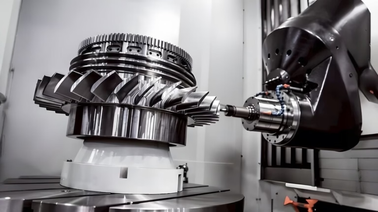
Milling Machines: Rotating Tool, Fixed Workpiece
A CNC mill spins a multi-flute cutter and moves it through the workpiece along linear axes. The part stays clamped to the table; the tool travels. That single fact explains most of what a mill is good at. Pockets, slots, flat faces, drilled hole patterns and contoured surfaces all come from a tool that can reach the feature from above or from the side.
Axis count is the main dividing line. A three-axis mill moves X, Y and Z only. A four-axis machine adds a rotary table, so the part can index to a new face without a second setup. A five-axis machine tilts and rotates the tool or the table at the same time, which lets a stubby cutter stay normal to a curved surface. On deep cavities, that rigidity is the difference between chatter and a clean wall.
Tool selection drives the result more than the machine does. A Ø10 mm carbide end mill in 6061 aluminum running 4,000–8,000 rpm removes material fast and holds Ra 1.6 μm without any special setup. Drop the same cutter into 17-4PH stainless and feed rates fall by half or more. Heat stays in the chip, not the part.
The limitation is reach and depth. Long tools deflect, so a 4:1 length-to-diameter ratio is a practical ceiling for tight tolerance work. Beyond that, either the geometry changes or the job moves to EDM. Tool access also decides whether one setup covers the part or a second operation is needed for the back side.
- 1Best forPrismatic parts: housings, brackets, plates, mold inserts, manifolds
- 2Typical tolerance±0.005 mm on critical features, with in-process probing
- 3Watch out forThin floors that deflect under clamping pressure
Turning: The Part Rotates, the Tool Follows
On a CNC lathe the workpiece spins and a single-point tool feeds along the axis of rotation. Any feature that is symmetric about a centerline falls naturally into this family: shafts, bushings, bolts, connectors, valve bodies and turned flanges. Cycle times are usually shorter than milling because the tool stays engaged through the whole pass.
A mill-turn center blurs the line. It starts as a lathe with a rotating spindle, then adds live tooling and a Y axis so the same setup can cut flats, cross-holes and slots. GreatLight runs 16 mill-turn centers, which removes the re-fixturing error you get when a turned part has to move to a mill for its secondary features.
Holding concentricity is the reason to pick turning over milling. A Ø30 mm shaft with three diameters and a thread can hold 0.01 mm total runout in one chucking. Mill the same part from bar stock and you fight setups. On long, slender shafts, though, a steady rest or a follow rest is mandatory; without support the part pushes away from the tool and the middle of the shaft goes oversize.
Boring is the internal version of the same motion. It opens an existing hole to size and location with a single-point tool, and it is the standard way to hit a bore tolerance after drilling. For bores under Ø6 mm, check that the boring bar actually fits before promising the tolerance.
- 1Best forRotational parts: shafts, sleeves, fittings, threaded components
- 2Typical tolerance±0.005 mm on diameter; 0.01 mm runout in one setup
- 3Watch out forBar stock remnants and chuck marks on finished surfaces
Plasma Cutting: Fast, Flat and Conductive Only
A CNC plasma cutter pushes an ionized gas jet through the work and melts a kerf, blowing the molten metal out the bottom. It only works on electrically conductive material: steel, stainless, aluminum, copper, brass. It does not touch plastics, composites or glass.
The process lives in sheet and plate work, not in precision parts. A typical cut runs 1,000–6,000 mm/min depending on thickness, and a 6 mm mild steel plate cuts cleanly at high speed. Edge quality lands around Ra 6.3–12.5 μm, with a slight bevel on the kerf and a heat-affected zone along the cut face. That is fine for a bracket blank or a gusset. It is not fine for a sealing surface.
The practical thickness ceiling depends on amperage. A 100 A unit handles roughly 25 mm mild steel; thinner material cuts faster and cleaner. Above 40 mm, edge squareness and dross start to become a problem, and a different process is usually cheaper than cleaning up the cut.
Use plasma to get a flat blank close to net shape, then finish critical edges on a mill. That combination is common in sheet metal fabrication: cut the profile, bend it, machine the mounting holes that carry a tolerance. Trying to plasma-cut a finished bearing bore is a mistake every shop makes once.
- 1Best forFlat plate and sheet blanks, gussets, base plates, weldments
- 2Typical tolerance±0.5 mm on profile; edge Ra 6.3–12.5 μm
- 3Watch out forHeat-affected zone and taper on thick plate
EDM: Sparks Instead of Cutting Force
Electrical discharge machining removes metal with controlled sparks between an electrode and the workpiece, submerged in dielectric fluid. There is no mechanical cutting force, which is the whole point. You can cut a hardened tool steel insert, a sharp internal corner, or a 0.2 mm slot in a part that would distort under a milling cutter.
Two variants cover most work. Wire EDM feeds a thin brass or coated wire through the part, producing a straight-sided through-cut with corner radii as small as the wire radius plus the spark gap. Sinker EDM burns a shaped electrode into the work to form a cavity, which is how many mold and die features get made. Both run slowly.
Accuracy is the trade for speed. Wire EDM holds ±0.005 mm routinely and can reach ±0.002 mm on a well-maintained machine with multiple skim passes. Surface finish improves with each pass, from Ra 3.2 μm on a rough cut down to Ra 0.2–0.8 μm after skimming. A part that takes four minutes on a mill can take two hours on a wire.
Only conductive materials work. That rules out most ceramics and all plastics. EDM also leaves a recast layer on the cut surface, typically 1–5 μm thick, which matters for fatigue-critical parts and for any surface that gets welded or coated. For those, plan a light finishing pass or a stress-relief step after EDM.
- 1Best forHardened steel, sharp internal corners, thin walls, micro features
- 2Typical tolerance±0.005 mm standard, ±0.002 mm on finish passes
- 3Watch out forRecast layer and slow removal rate
Additive: Building the Part Layer by Layer
Metal 3D printing reverses the logic of the other four families. Instead of removing material, it fuses powder layer by layer: SLM and SLS melt metal powder with a laser, while SLA cures resin. Part complexity costs almost nothing extra, because a hidden internal channel is just as easy to print as a flat face.
The trade is surface finish and anisotropy. As-built metal surfaces land around Ra 8–15 μm and usually need bead blasting or machining on mating faces. Properties vary by build direction, so a part loaded in the Z axis behaves differently from the same geometry loaded in X. Design for the build orientation, not against it.
This is where conformal cooling and lightweight lattice structures earn their place. A mold insert with cooling channels that follow the cavity curve can cut cycle time noticeably compared with straight drilled channels. A bracket with internal lattice replaces solid material without losing stiffness. Neither geometry is machinable by conventional means.
Use additive for prototypes and low-volume complex parts, then switch to casting or machining once volume climbs. GreatLight runs stainless, aluminum alloy, titanium alloy and mold steel printing, so early-stage geometry can be validated before tooling is cut. For a part with simple geometry and a 10,000-piece annual volume, printing it is the wrong call.
- 1Best forConformal cooling, lattices, consolidated assemblies, prototypes
- 2Typical tolerance±0.1 mm as-built; machine critical faces after printing
- 3Watch out forAnisotropic properties and support removal on internal channels
Comparing the 5 Common Types of CNC Machines
Match the part geometry to the process before you request a quote.
| Machine type | Material removal | Typical tolerance | Best-fit parts |
|---|---|---|---|
| CNC milling | Rotating cutter, 3–5 axes | ±0.005 mm | Prismatic housings, plates, pockets |
| CNC turning | Single-point tool, part rotates | ±0.005 mm | Shafts, bushings, threaded fittings |
| Plasma cutting | Ionized gas jet, conductive only | ±0.5 mm profile | Plate blanks, gussets, weldments |
| EDM (wire and sinker) | Sparks in dielectric fluid | ±0.005 mm, ±0.002 mm finish | Hardened steel, sharp corners, micro slots |
| Additive (SLM, SLS, SLA) | Laser fuses powder, layer by layer | ±0.1 mm as-built | Conformal cooling, lattices, prototypes |
Which Machine Type to Pick
If the part is prismatic and needs tight tolerance, choose milling. If it is rotational, choose turning. Use plasma only for flat blanks you will finish later, EDM for hardened steel and sharp internal corners, and additive when the geometry cannot be machined at all.
Frequently Asked Questions
Can one part need more than one machine type?
Yes, and most do. A machined housing often starts as a plasma-cut plate, gets its pockets milled, its bores turned or bored, and its sharp internal corner finished on wire EDM.
Each process handles the feature it is best at. Trying to force everything onto one machine usually costs more in cycle time or in extra setups.
How do I choose between 3-axis and 5-axis milling?
Start with tool access. If every feature can be reached from one direction, 3-axis is cheaper and faster to program. If the part has angled faces, deep contoured pockets or features on five sides, 5-axis removes setups and holds position between features.
Five-axis also lets a short, rigid cutter stay normal to a curved surface, which improves finish on complex geometry.
Is EDM ever faster than milling?
Rarely. EDM removes material slowly, so it is not a roughing process. It wins when the material is too hard for carbide, when the corner radius is smaller than any cutter can reach, or when cutting force would distort a thin wall.
For a hardened die insert with a sharp internal corner, wire EDM is often the only process that holds the tolerance.
What surface finish can additive parts achieve?
As-built metal surfaces land around Ra 8–15 μm and carry visible layer lines. Bead blasting, tumbling or polishing brings that down, and machining a mating face after printing gives you a normal machined tolerance there.
Plan the finishing operation into the design from the start rather than trying to print a sealing surface directly.
Do all five machine types need the same material?
No. Plasma and EDM require conductive material. Milling and turning handle aluminum, stainless, steel, copper, brass, titanium and plastics. Additive uses metal powder or resin, so the material must exist in a printable grade.
GreatLight processes aluminum 6061, 7075 and ADC12, stainless 303 to 17-4PH, titanium TC4, Inconel and engineering plastics including PEEK.
How tight can tolerances get across these processes?
Milling, turning and EDM hold ±0.005 mm on critical features, and EDM finish passes can reach ±0.002 mm. Plasma and as-built additive sit far looser, in the ±0.1 mm to ±0.5 mm range.
Where the tolerance is tight, the feature usually gets machined even if the blank came from plasma or printing.
Send Your Drawing, Get a Process Recommendation
Upload your files and our engineers will tell you which machine type fits, with a quotation and free DFM analysis within 12 hours.
12-hour quote100% inspectionNDA on request
More Machining Notes
We publish setup notes, tooling trials and inspection data from the factory floor.











