
What Can You Use a CNC Machine For?
Short answer: any part that starts as a solid block of metal or plastic and needs accurate geometry can be milled or turned. This page is for engineers and buyers who need to judge whether a design belongs on a CNC machine, what tolerance range is realistic, and when another process wins. We cover part families, material limits, and the cost drivers that decide the answer.
In this article
- 1
- 2
- 3
- 4
- 5
- 6
What a cnc machine for cutting actually removes
A CNC machine is a controlled cutting system. A spindle holds a rotating tool, a table or chuck holds the workpiece, and the controller moves one against the other along programmed axes. The tool removes material in chips. Nothing is formed or cast. The final shape exists because everything that should not be there was cut away.
That single fact explains most of what you can and cannot do. You can add pockets, holes, threads, slots and radii wherever the tool can reach. You cannot leave a hollow internal cavity with no opening, and you cannot beat a mold on a hundred thousand identical thin shells. The process pays off when geometry is complex, volume is low to medium, or the material is hard enough that casting and stamping tools would cost more than the parts.
Repeatability comes from the program, not the operator. Once a setup is proven, the same G-code produces the same part on the next shift. That is why CNC holds ±0.005 mm on critical features while manual machining on the same part drifts with tool wear and hand pressure. The controller also records axis positions, so a dimension that was right on part one stays right on part five hundred.
- 1Subtractive by natureMaterial is removed, so internal voids need an access path.
- 2Program-drivenAccuracy repeats without relying on operator feel.
- 3Tool-reach limitedDeep, narrow pockets need long tools, which deflect more.
Which part families a cnc machine for metal is built around
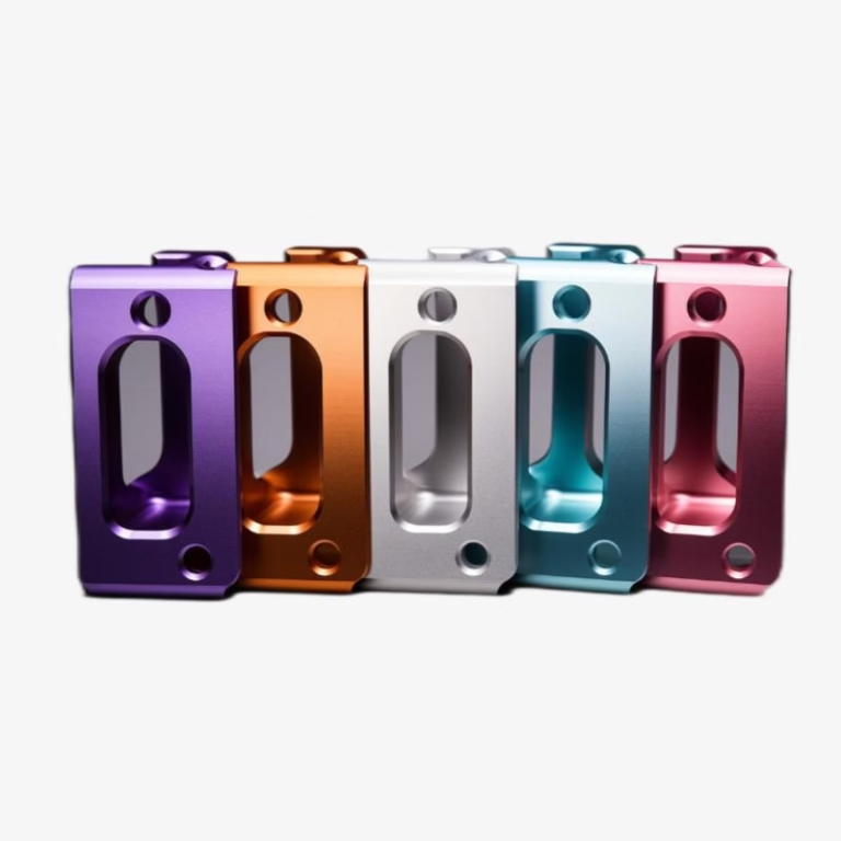
Structural and load-bearing parts are the classic fit. Brackets, housings, manifolds, engine and motor mounts, landing gear links, robot arms and gearbox covers. These usually need flat mounting faces, precise hole patterns and a few tight bores. Five-axis work pays off when the part has angled faces or curved transitions that would need three separate setups on a three-axis mill.
Fluid and motion parts are the second family. Valve bodies, pump housings, impeller blanks, pistons, shafts, bushings and lead screw nuts. Here the critical features are usually bores, seal grooves and concentricity between two diameters. Turning centers and mill-turn machines handle these in one setup, which keeps the bore and the outer diameter on the same centerline instead of stacking two setup errors.
Tooling and short-run production parts are the third. Injection mold cores and cavities, die casting inserts, jigs, fixtures, gauges and check blocks. These are often one-off, made from tool steel or 7075 aluminium, and need to hold size after heat treatment. The machining is not the hard part. Planning for the shrink and the finishing allowance is.
Prototype and bridge parts are the fourth. A design that will eventually be die cast or injection molded often gets its first twenty units machined. You get real material properties and real fit checks in days rather than waiting months for a tool. The trade-off is a higher unit cost, which is acceptable at low volume and painful past a few thousand units.
- 1Structural partsBrackets, housings, mounts, robot links.
- 2Fluid and motion partsValve bodies, shafts, bushings, seal bores.
- 3ToolingMold inserts, jigs, fixtures, gauges.
- 4PrototypesBridge parts before hard tooling is cut.
Material limits: what cuts well and what fights back
Aluminium is the default for machined parts. Grades 6061 and 7075 cut fast, hold tight tolerances and take anodizing well. 6061-T6 is the workhorse for housings and brackets. 7075 gives roughly double the yield strength but is less weldable and more prone to stress corrosion. If a part needs both strength and a clean anodized finish, 6061 usually wins on cost.
Stainless and steel follow. Grades 303 and 304 machine cleanly for shafts and fittings. 316L is the choice for medical and marine parts because of corrosion resistance, though it work-hardens and needs slower feeds. 17-4PH gives high strength after aging and is common in aerospace and medical instruments. Tool steels such as 4130, 4140 and 4340 are machined in the annealed state, then heat treated, which means you must plan a finishing allowance.
Titanium and nickel alloys are where geometry gets expensive. Ti-6Al-4V and Inconel keep strength at high temperature but conduct heat poorly, so the cutting edge absorbs the heat. Tool life drops and cycle time climbs. These are still machinable, but a design that needs a deep pocket in Inconel should be questioned before it is quoted.
Plastics behave differently. POM and PEEK hold dimensions well and are common for insulators and bushings. ABS, PC and PMMA are easy to cut but move with temperature and clamp pressure. Carbon fibre machines cleanly but the dust is abrasive, so tool wear is high. For soft plastics, a light finishing pass and sharp tooling matter more than spindle speed.
- 1Easy group6061, 7075, 303, 304, brass, POM.
- 2Careful group316L, 17-4PH, 4140, titanium.
- 3Hard groupInconel, hardcoat tool steel, carbon fibre.
How tolerance and finish decide the answer
Not every part needs the tightest tolerance on the drawing. A mounting hole at ±0.1 mm costs far less than the same hole at ±0.01 mm, because the tight version needs a separate finishing pass, sometimes a reaming step, and more inspection time. Before quoting, we look at which dimensions actually locate the part and which are just clearance.
Surface finish follows the same logic. As-machined surfaces sit around Ra 1.6–3.2 μm, which is fine for most brackets and covers. Sealing faces and sliding surfaces usually need Ra 0.8–1.6 μm. Bearing bores, hydraulic seal grooves and optical mounts can need Ra 0.2–0.8 μm, which means slower finishing passes or a subsequent lapping step. Each step down in roughness adds time.
Feature size sets a floor too. A 0.5 mm end mill can cut a small slot, but it breaks easily and must run slowly. Deep pockets with a high depth-to-diameter ratio force long, thin tools that deflect, so the wall may not be straight. If a design calls for a 20 mm deep pocket with a 2 mm corner radius, expect either a slower cycle or a redesign with a larger corner.
The practical rule we give customers: put the tight tolerance only where the part functions. Two or three critical features at ±0.005 mm are normal. A whole drawing at ±0.005 mm usually means the designer has not decided which surfaces matter, and the price reflects that uncertainty.
- 1Tolerance drives costEach tightening adds a pass and inspection time.
- 2Finish is separateRa 0.2–0.8 μm needs slower, lighter cuts.
- 3Small tools deflectDeep narrow pockets weaken accuracy.
Setup count is the hidden cost driver
Every time a part is unclamped and turned, the new setup adds an error. On a three-axis mill a part with features on five faces might need four setups. On a five-axis machine the same part can often be done in one or two. That is not a marketing point. It changes both the tolerance stack and the labor hours in the quote.
For a single prototype, setup dominates the price. The spindle may run for twenty minutes while the programmer and operator spend two hours on fixtures and offsets. At ten parts the setup is spread thinner. At a thousand parts it is almost irrelevant, and cycle time takes over. This is why unit price drops sharply between one and fifty pieces, then flattens.
Fixtures matter as much as machines. A thin wall part clamped too hard will spring back after release and measure out of tolerance even though the cut was correct. Soft jaws, vacuum plates and custom supports are not extras. They are the reason a part holds size. A supplier that quotes without asking about wall thickness and clamping is guessing.
This is also where size limits enter. A part that fits in a 500 × 500 × 450 mm envelope can run on many machines. A part near 4,000 mm needs a large-travel machine and often a different fixturing plan, because thermal growth over that length becomes measurable. GreatLight runs 127 high-precision CNC machines, with 16 simultaneous five-axis centers and a 4,000 mm maximum processing size, so both ends of that range are covered in house.
- 1Fewer setups, tighter stackFive-axis reduces re-clamping errors.
- 2Setup spread by volumeCost falls fast from 1 to 50 pieces.
- 3Fixtures hold toleranceThin walls need soft jaws or vacuum.
CNC versus other processes by part and volume
Use this to pick a process before you request a quote.
| Part situation | CNC fit | Better alternative | Why |
|---|---|---|---|
| 1–100 complex metal parts | Strong fit | None needed | No tooling cost, tight tolerance |
| 50,000 thin plastic shells | Poor fit | Injection molding | Cycle cost dominates at volume |
| Hollow closed cavity | Poor fit | Casting or 3D printing | Tool cannot reach inside |
| Large flat sheet panels | Weak fit | Sheet metal fabrication | Bending is faster and cheaper |
| Sealing face at Ra 0.4 μm | Strong fit | None needed | Finishing passes reach the spec |
| Prototype before die casting | Strong fit | None needed | Real material, no tooling wait |
| Part near 4,000 mm long | Strong fit | None needed | Large-travel machines available |
| Thin shell under 0.8 mm wall | Weak fit | Sheet metal or molding | Clamping distorts the part |
When CNC is the right answer, and when it is not
Choose CNC when the part is complex, the volume is under a few thousand, or the material is too hard to mold or stamp cheaply. Choose molding, casting or sheet metal when geometry is simple, walls are thin, or volume is high enough that tooling cost disappears into the unit price. If your part sits in the middle, send the drawing and we will say which side it falls on before quoting.
Questions engineers ask before sending a drawing
What is the smallest feature a CNC machine can cut?
It depends on tool diameter and depth. A 0.5 mm end mill can cut a small slot, but only to a shallow depth before it breaks. As a rule, keep pocket depth under three times the tool diameter, or accept a slower cycle and a higher risk of scrap.
Corner radii matter too. A pocket with a 2 mm corner needs a 4 mm cutter at minimum. If the drawing calls for a sharp internal corner, an EDM or a redesign is usually cheaper than forcing a tiny tool.
Can CNC hold tolerance on thin-wall parts?
Yes, but the wall thickness sets the limit. Above roughly 1 mm in aluminium, normal fixturing works. Below that, the part moves when the clamp releases, so soft jaws, vacuum plates or sacrificial supports are needed.
The cut itself is rarely the problem. Clamping pressure and residual stress from the material removal are. A supplier that ignores this will ship a part that measures correctly on the machine and out of tolerance on the bench.
Which materials are hard to machine and why?
Titanium and nickel alloys such as Inconel are the usual answer. They conduct heat poorly, so the cutting edge gets hot and wears fast. They also work-harden, meaning a light rubbing cut makes the next pass harder.
Stainless 316L sits in the middle. It machines fine with correct feeds and coolant, but it work-hardens if the tool dwells. The fix is a constant feed and a sharp edge, not a slower speed.
How do I decide between 3-axis and 5-axis machining?
Count how many faces need features. If all the critical work is on one face, a three-axis machine is enough and cheaper. If features sit on angled faces, or the part has curved surfaces that must blend smoothly, five-axis reduces setups and improves the tolerance stack.
Five-axis also helps with undercuts and tool access, because the table tilts to present the surface to a shorter, stiffer tool. That improves both finish and cycle time on complex geometry.
What information should be on a drawing for an accurate quote?
Give the material grade, the critical tolerances, the surface finish callouts and the quantity. Mark which dimensions are functional and which are clearance. Add a 3D model if you have one, because it removes ambiguity about blend radii and free-form surfaces.
If heat treatment or surface finishing is needed, say so up front. Those steps change the allowance on the drawing and the order of operations, and leaving them out usually means a revised quote later.
Send the drawing and get a straight answer
We review the geometry, material and tolerance before quoting, and tell you if another process would serve you better. Quotation and free DFM analysis within 12 hours.
12-hour quote100% inspectionNo MOQNDA on request
More from the shop floor
We publish setup notes, tooling trials and inspection data from the factory floor.











