
What Does CNC Machine Stand For?
CNC stands for Computer Numerical Control: a machine that reads a program of coordinates and drives cutting tools along those coordinates instead of a hand on a crank. This page explains the acronym, how the control loop works, what each axis really does, and the cases where CNC is the wrong process. Written for design and process engineers who need to judge a part, not just define a term.
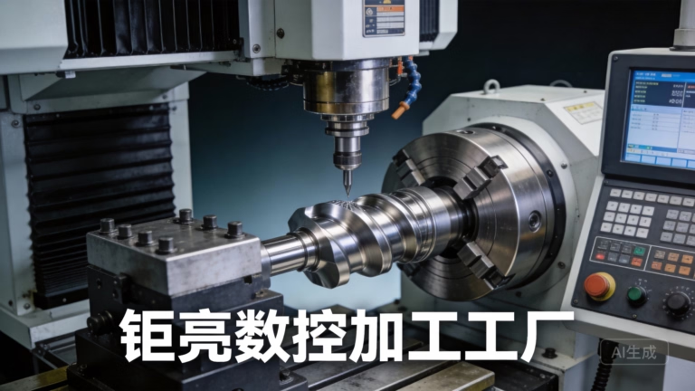
What Does CNC Machine Stand For, Word by Word
Computer Numerical Control. Three words, each doing work. Computer means the motion comes from a stored program, not from a machinist turning handwheels. Numerical means every position is written as a number in a coordinate system, so a feature exists as values before any metal is cut. Control means the machine holds the tool on that path and corrects it thousands of times per second.
That last point is what separates CNC from a power feed. A manual mill with a motorized table still depends on a person watching a dial. A CNC machine compares the commanded position with the measured position and adjusts the servo until the error falls inside the tolerance window. On our 5-axis centers that loop runs fast enough to hold ±0.005 mm on production parts.
The word numerical also explains the workflow. A CAD model is processed in CAM software, which outputs a toolpath and then a program of G-code and M-code lines. G-code sets the geometry: feed rate, spindle speed, coordinates. M-code handles the machine logic: coolant on, tool change, spindle stop. The operator sets the work offset and the tool lengths, then the controller runs the program.
So when a buyer asks what does cnc machine stand for, the practical answer is a machine that turns a digital file into repeatable metal removal. Nothing about the acronym promises precision on its own. Precision comes from the machine structure, the tooling, the fixtures, and how well the program matches the part.
How the Control Loop Turns Numbers into Cuts
The controller reads one block of the program at a time and sends target positions to the servo drives. A rotary encoder or linear scale reports where the axis actually is. The drive compares the two and corrects. This happens continuously, so a toolpath is never followed perfectly. It is followed closely enough to land inside the tolerance band.
Feed rate, spindle speed and tool geometry decide how much heat and force the cut creates. Push a 12 mm end mill too hard in 304 stainless and the tool deflects, the wall goes tapered, and the surface finish drops to Ra 3.2 μm or worse. Run it at the right chip load and you get a stable cut with a predictable finish in the Ra 0.8–1.6 μm range.
Rigidity is the other half of the story. A machine tool is a spring. Cutting force bends it, and the bend shows up in the part. That is why the same program cuts differently on a light benchtop mill and on a 3-axis machine with a heavy cast frame and preloaded linear guides. The numbers are identical. The deflection is not.
This is also where thermal effects enter. Spindles warm up, ballscrews grow a few micrometres, and the first parts of a shift can drift. Shops that hold tight tolerances let the machine warm up, run a warm-up program, and check a test cut before releasing production. A machine that reads perfect numbers can still cut an imperfect part.
What the Axes Actually Do, and When You Need More
X, Y and Z are linear. On a 3-axis mill the tool approaches from one direction, so any face that points away from the spindle needs a second setup. Each setup adds a work offset, a re-clamp and a fresh chance for positional error. On a ±0.005 mm part, a second setup is often the largest single error source.
A 4-axis machine adds rotation about one axis, usually A around X. The part can be indexed to several faces without being unclamped. Think of a shaft with cross-drilled holes at four angles, or a bracket that needs features on two perpendicular faces. One program, one clamp, one datum.
A 5-axis machine adds a second rotary axis, so the tool can tilt relative to the part. That lets a short, stiff tool reach a deep pocket wall or a contoured surface at the correct angle. On impellers, turbine blades and organic housings, 5-axis simultaneous motion makes the part machinable at all. On a simple plate with drilled holes, it adds nothing.
There is a real cost to more axes. Programming time goes up, collision checking matters, and not every shop has the post-processors or the operators to run it well. Choose the axis count from the geometry and the datum strategy, not from the machine list.
- 13-axisPrismatic parts, one dominant face, simple datums.
- 24-axisShafts, cross features, features on multiple sides of a box.
- 35-axisContoured surfaces, deep pockets, one-setup complex geometry.
CNC Milling, Turning and Mill-Turn: Same Idea, Different Motion
A CNC mill spins the tool and moves it through the work. That suits pockets, slots, faces and complex 3D shapes. A CNC lathe spins the work and moves a single-point tool along it. That suits anything round: shafts, bushings, flanges, threaded fittings. The physics differ, the control logic is the same.
A mill-turn center does both in one machine. A turned blank can be milled, cross-drilled and tapped without being moved to a second machine. For a hydraulic manifold or a medical instrument body, that removes two setups and two chances for error. Our shop runs 16 mill-turn centers for exactly this class of part.
The choice is not a preference. If the part is mostly a surface of revolution, turning is faster and cheaper. If it is mostly prismatic, milling wins. If it is both, mill-turn or a 5-axis mill with a rotary table usually beats two separate operations.
Size caps the decision too. Our largest travel is 4,000 × 400 × 150 mm for long parts, with 750 × 1,150 × 550 mm and 600 × 600 × 600 mm envelopes for medium work and 500 × 500 × 450 mm for compact parts. A part that does not fit the envelope does not get machined on that machine, no matter how simple it looks.
Where CNC Stops Making Sense
Thin walls are the classic limit. A 0.5 mm aluminum wall will chatter and deflect under normal cutting forces, so the machinist has to take light passes, and the part may still move after clamping is released. Below a certain wall thickness, the process cannot hold the geometry reliably.
Deep, narrow features are another. A pocket 10× deeper than the tool diameter needs a long, thin tool, and a long, thin tool deflects. Rough it out, then use a smaller tool for the corners, or change the design to a wider radius. A corner radius smaller than the tool radius cannot be cut at all.
Hardness matters as well. Above roughly 45 HRC on the part, carbide tooling wears fast and the finish suffers. Pre-hardened tool steels and hardened inserts usually go to grinding or EDM instead. Titanium and Inconel are machinable, but they demand low cutting speeds and generous coolant, which raises cycle time.
Volume and shape also matter. A thin-walled enclosure with a large flat face is often better as sheet metal. A hollow lattice with internal channels is often better printed. CNC removes material from stock, so it wins where the part needs tight tolerances, good surface finish, solid material properties, or a proven material specification.
Which Process Fits Which Part
Use this as a first screen before you send a drawing.
| Part trait | CNC machining | Better alternative |
|---|---|---|
| Prismatic, tight tolerance | Yes, ±0.005 mm achievable | — |
| Surface of revolution | Turning or mill-turn | — |
| Wall under 0.5 mm | Chatter risk | Sheet metal or molding |
| Corner radius below tool radius | Not cuttable | EDM or design change |
| Hardened above 45 HRC | Tool wear | Grinding or EDM |
| Internal channels or lattice | Limited | Additive then finish |
| Large flat panels | Slow, wasteful | Sheet metal fabrication |
| One-off prototype | No MOQ, 3–5 days | — |
The Short Version
If your part is solid, needs tight tolerances and a real material spec, use CNC. If it is thin, hollow, or mostly a flat panel, use sheet metal or molding instead. Five-axis only pays off when the geometry or the datum strategy demands it.
Questions Engineers Ask Next
Is CNC the same as automation?
No. CNC automates the motion of one machine tool, not a whole factory. The program tells the axes where to go. Loading, clamping, tool changes between parts and inspection are often still manual or handled by separate equipment.
A cell with a robot loading a CNC mill is automated machining, but the CNC controller itself only governs the cut.
Does more axes always mean better parts?
No. Five-axis motion reduces setups and lets a stiff tool reach angled surfaces, which helps complex geometry. On a simple plate it adds programming time and cost without improving the part.
Pick the axis count from the part geometry and datum strategy. If two setups on a 3-axis machine can hold the tolerance, that is usually the cheaper route.
What tolerance can CNC actually hold?
On production parts we work to ±0.005 mm (about ±0.0002 in) when the geometry, material and fixturing support it. Thin walls, long slender features and hard materials tighten the real limit, not the machine spec sheet.
Send the functional tolerances, not just a blanket callout. The features that matter can get the tight band, and the rest can run looser.
How do surface finish and tolerance interact?
They trade off. A finishing pass with a small stepover improves the finish toward Ra 0.2–0.8 μm but takes more cycle time. As-machined surfaces sit around Ra 1.6–3.2 μm.
Tell us where the finish matters. Seal faces, bearing bores and sliding surfaces usually do. Cosmetic internal faces usually do not.
What do I need to send for a quote?
A STEP or native CAD file, the material, the critical tolerances, the finish and the quantity. If the drawing has a GD&T frame, include it so the datums are clear.
We return a quotation and a free DFM analysis within 12 hours, and production can start within 24 hours. No minimum order quantity, from one prototype to 10,000+ parts.
Can CNC cut any material?
It cuts most metals and plastics, but the parameters change a lot. Aluminum 6061 and 7075 run fast. Stainless 316L and titanium Ti-6Al-4V run slow with heavy coolant. Inconel is machinable but costly in cycle time.
If the material is abrasive or very hard, the tooling cost and finish may point to a different process.
Send the Drawing, Get a Real Answer
Upload your CAD file and we will confirm the process, the achievable tolerance and the finish, with a free DFM analysis in 12 hours.
12-hour quoteNo MOQ100% inspectionNDA on request
More from the shop floor
We publish setup notes, tooling trials and inspection data from the factory floor.











