
What Are Counter Pulls on a CNC Machine?
A counter pull is the self-induced force that drags a tool or workpiece off its commanded path. This page explains where it comes from, how to measure it, and when it matters at ±0.005 mm. Written for engineers who need to judge a part before quoting it.
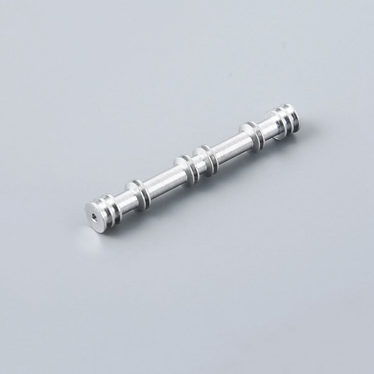
Where Counter Pulls on a CNC Machine Come From
The term does not appear in a machine tool textbook. It is shop-floor shorthand. Counter pulls on a cnc machine describe forces the machine generates against itself: the spindle is where the program puts it, yet the material or the tool still shifts. The cut path and the real path stop being the same line.
On a rigid setup with light finishing passes, this shift may be a few micrometres and nobody notices. On a thin wall, a long boring bar, or a four-flute cutter buried in 7075, the same forces move the surface by tenths of a millimetre. That is the difference between a part that fits and a part that gets reworked.
Two things make counter pulls different from ordinary deflection. First, they are self-induced: the cutting process creates the load that moves the tool. Second, they change as the cut progresses, so a single spring-pass calculation rarely predicts the final wall thickness.
The practical question is not whether counter pulls exist. It is whether the part in front of you is sensitive enough that they will show up in the inspection report.
- 1Static deflectionConstant load bends the tool or part by a fixed amount.
- 2Dynamic deflectionLoad varies with each tooth, so the surface ripples.
- 3Coupled pullThe cut changes the geometry, which changes the load again.
- 4Thermal driftHeat grows the part during the pass, not just at the end.
The Five Forces Behind the Pull
Cutting force is the obvious one. The tangential and radial components push the tool away from the wall. A Ø16 mm end mill at 0.1 mm per tooth in 6061 might see 400–700 N of radial load. The tool shank, holder, and spindle all bend under it, and the sum of those bends is a fraction of a millimetre.
Residual stress in the workpiece is the second. Rolled plate and extruded bar hold internal stress. Remove material from one side and the balance is disturbed, so the part bows as the cut releases material. This is why a 4140 plate can measure flat before machining and 0.15 mm out of flat after.
Clamping is the third. A vise or fixture applies its own load. When the tool relieves the metal around a clamped boss, the part springs to a new shape. Release the clamp and it moves again. The operator sees a good dimension on the machine and a bad one on the bench.
Thermal growth and tool wear round out the list. A spindle running at 12,000 rpm warms the tool and the part. The same cutter that holds 0.02 mm at 09:00 may hold 0.04 mm at 15:00 because the edge has rubbed. Neither is a counter pull in the pure sense, but both read the same way on the inspection sheet.
- 1Cutting forceRadial load bends tool, holder, and spindle.
- 2Residual stressMaterial balance changes as metal is removed.
- 3ClampingFixture load releases when the cut frees the part.
- 4Thermal and wearHeat and edge wear shift the dimension over a shift.
Which Parts Are Sensitive, and Which Are Not
Thin walls are the classic case. A wall under 1 mm on a 50 mm tall feature has very little section to resist a side load. The tool pushes it, the wall springs back, and the finished thickness varies with depth. If the wall also has a tight flatness callout, the two requirements fight each other.
Long tools are the second group. A Ø6 mm cutter hanging 60 mm out of the holder has a stiffness that falls with the cube of the length. Doubling the gauge length cuts stiffness by roughly eight times. Deep pockets, deep bores, and small internal channels all fall into this group.
Parts with asymmetric material removal are the third. A housing that is solid on one side and open on the other will move when the heavy side is machined. The same is true of long shafts that get a keyway on one side or a flange that is faced from one direction only.
Some parts are simply not sensitive. A thick block with generous walls, short tools, and a stable vise will hold ±0.005 mm without special effort. Spending time on stress relief or a five-axis setup for that part adds cost with no benefit. Judging which group a part belongs to is the real engineering decision.
- 1Thin wallsBelow 1 mm section, side load dominates the result.
- 2Long toolsStiffness drops with the cube of overhang.
- 3Asymmetric removalOne-sided cuts release the stress balance.
- 4Deep featuresSmall bores and channels hide the deflection.
What Five-Axis Setup Changes
Counter pulls on a cnc machine are often worst when a part needs several setups. Each new setup re-clamps the part and re-introduces the same release error. A five-axis machine that reaches all the features in one setup removes that source. On a housing with bores on three faces, this alone can cut the position error by half.
Five-axis also lets the tool approach a wall at an angle. A wall cut with the tool axis tilted 15–30° puts part of the load into the stiff direction of the cutter. The wall still moves, but less. On thin aerospace ribs, this is the difference between a straight wall and a tapered one.
It does not remove residual stress. If a 7075 plate is heavily machined on one side, it will still bow. The fix there is stress-relieved stock, balanced material removal, or an intermediate stress-relief step. No machine geometry replaces that.
With 16 simultaneous 5-axis machining centers and a maximum processing size of 4,000 mm, we can hold a part in one setup where a three-axis route would need four. For a part with a tight true-position callout, that is usually the deciding factor.
- 1One setupRemoves re-clamping error between operations.
- 2Tilted approachPuts load into the stiff axis of the tool.
- 3Short toolsBetter reach with less overhang on deep faces.
- 4Not a stress cureResidual stress still needs a material fix.
When a Counter Pull Cannot Be Machined Away
Some geometry has no stable cutting window. A 0.3 mm wall on a 40 mm tall feature in aluminium will move under almost any side load. You can reduce the load, support the wall from behind, or fill it with a low-melt alloy, but the finished part is still fragile. Grinding or EDM may be the better route.
Material choice sets the limit too. Titanium and Inconel cut with higher forces, so the same wall that holds in 6061 may not hold in Ti-6Al-4V. The modulus is higher, but the cutting pressure is far higher as well. We treat titanium thin-wall work as a separate process, not a variant of the aluminium job.
Tolerance interacts with all of this. Holding ±0.005 mm on a stable part is routine. Holding it on a 0.8 mm wall with a 30 mm depth means the process has to be built around the pull, not the drawing. That usually means more passes, slower feed, and a longer cycle.
The honest answer for some designs is that a small change in the drawing is cheaper than a difficult process. Thickening a wall from 0.8 mm to 1.5 mm, or adding a rib, can remove the problem before the first chip.
- 1Very thin wallsBelow 0.5 mm, the part is unstable at any feed.
- 2High-strength alloysTi and Inconel raise cutting force sharply.
- 3Deep, narrow featuresTool overhang grows faster than the section.
- 4Redesign beats processA thicker wall or a rib removes the risk.
How to Prove the Pull and Fix It
Five checks we run before and during a tight-tolerance job.
- 1Measure before, not afterRecord flatness, wall thickness, or bore size on the raw stock and on the first finished piece. The difference is the pull plus any stress release.
- 2Cut a test wallMachine a single wall at the same depth and width as the real feature. Measure it at three heights. A taper over 0.02 mm points to tool deflection.
- 3Split the passesTake a roughing pass at 0.5–1.0 mm radial depth, then a finishing pass at 0.1–0.2 mm. The light pass cuts the springback and leaves the dimension stable.
- 4Change the holding, not the feedAdd supports under thin floors, use soft jaws, or move the clamp away from the finished face. Most spring-release errors are fixture errors.
- 5Control the heatWarm the spindle for 20–30 minutes, keep coolant on the part, and finish critical features in the same shift. Thermal drift of 0.01–0.03 mm over a long run is normal.
- 6Verify on the machineProbe the feature before unclamping. If it reads good in the vise and bad on the bench, the error is in the release, not the cut.
Reading the Symptom Against the Cause
| What you see | Most likely cause | First check |
|---|---|---|
| Wall thin at the top, thick at the bottom | Radial cutting force | Reduce radial depth of cut, check runout |
| Part bows after the vise is released | Clamping load | Loosen the vise and re-measure the same face |
| Flat plate turns concave after facing | Residual stress | Stress-relieve or machine both sides evenly |
| Size drifts over a long run | Thermal growth or tool wear | Log spindle hours, inspect the edge |
| Bore comes out tapered | Long boring bar deflection | Shorten the bar, take two passes |
| Rippled surface at one spindle speed | Dynamic chatter | Adjust rpm or tooth count, not feed alone |
The Verdict
If the part has thick walls and short tools, run it on a three-axis machine and hold ±0.005 mm. If it has thin walls, deep features, or several faces to locate, put it on a five-axis machine in one setup and cut light finishing passes. If the wall is under 0.5 mm, change the drawing before you change the process.
Counter Pulls on a CNC Machine: Common Questions
Is counter pull a real machine tool term?
It is shop-floor language, not a standard term. There is no entry for it in machining handbooks. What it describes is real: self-induced forces that move the tool or the workpiece off the commanded path.
If you need a formal name for the effect, call it static and dynamic deflection, or springback after clamp release. The measurement and the fix are the same either way.
How do I measure a counter pull?
Measure the feature before unclamping and again after. The difference is the release movement. For tool deflection, cut a test wall and measure the taper from top to bottom over the full depth.
A probe on the machine gives the in-vise number in a few seconds. That single reading separates a cutting problem from a clamping problem.
Can I compensate for deflection in the CAM program?
Yes, for a known, repeatable load. Tool deflection tables can offset the path by 0.02–0.05 mm on a finishing pass. The limit is that the load changes as the wall gets thinner and as the tool wears.
Compensation is a fine adjustment, not a cure. Fix the setup and the pass strategy first, then trim the last few micrometres in CAM.
Does coolant reduce the pull?
It reduces the thermal half of it. Flood coolant keeps the part and the tool closer to room temperature, so the dimension drifts less over a long run.
It does nothing for cutting force or residual stress. Those need a lighter pass or different stock.
What wall thickness is safe at ±0.005 mm?
There is no single number, because the answer depends on wall height, tool overhang, and material. As a rule, a wall of 2 mm or more with a short tool is comfortable. A 1 mm wall at 30 mm tall needs split passes.
Below 0.5 mm, we quote the job with a process review first. The tolerance may be achievable, but the cycle time and the risk go up sharply.
Do you inspect for this before shipment?
Every part gets 100% inspection before shipment, with raw material check, in-process monitoring, and a final inspection. Reports are available on request.
For thin-wall work we also record the in-process dimensions at each pass, so the customer can see where the movement happened if a feature is marginal.
Send the Drawing, Get a Process Answer
We review wall thickness, tool reach, and setup count before quoting, so the price reflects the process the part actually needs. Quotation and free DFM analysis within 12 hours.
12-hour quote100% inspectionNo minimum order quantity
More Machining Notes
We publish setup notes, tooling trials and inspection data from the factory floor.











