
What Is a CNC Machine in Hindi? A Working Explanation
A CNC machine is a machine tool that follows a stored program instead of a handwheel. This page explains the acronym, how the controller turns a CAD model into motion, and where the process stops making sense. Written for engineers and buyers who need to judge a part, not memorize a definition.
In this article
- 1
- 2
- 3
- 4
- 5
- 6
- 7
What the Acronym Actually Means
CNC stands for computer numerical control. The name describes the control loop, not the cutting. A machinist no longer turns a handwheel to move the table; a controller reads a program of coordinates and drives the axes to those points. The metal removal still happens with a spinning cutter against a workpiece, exactly as it did on a manual mill.
The word numerical matters. Every position, feed rate and spindle speed in the program is a number. Because the moves are numbers, they repeat. Run the same program twice on the same machine and you get the same geometry, within the machine's own repeatability. That repeatability is the real product of CNC, more than speed.
You will see a cnc machine in hindi described as automatic. Automatic is too vague to be useful. A better working definition: a machine tool whose axis motion, spindle speed and tool changes are commanded by a program that can be edited, stored and re-run. Everything else follows from that.
If you are sourcing parts, the acronym tells you one useful thing. The geometry you designed will be reproduced by a machine that never gets tired and never re-reads a drawing differently at 4 pm. That is the property you are buying.
- 1ComputerThe controller, not a desktop PC
- 2NumericalCoordinates, feeds and speeds as numbers
- 3ControlClosed-loop feedback on axis position
From CAD File to Part: How the Motion Is Generated
The chain has four links: CAD model, CAM toolpath, post-processed G-code, machine controller. Each link can introduce error. A model with an open surface will not produce a clean toolpath. A toolpath built on the wrong stock size will cut air or crash.
CAM software converts the model into tool motions. You choose a cutter, a stepover, a stepdown and a feed rate. The software then decides how many passes it takes to clear the material. Thin walls, deep pockets and small internal radii are where this decision gets hard.
The post-processor translates the generic toolpath into the dialect your controller understands. Fanuc, Siemens, Heidenhain and Mitsubishi all read G-code, but their canned cycles and macros differ. A program posted for the wrong controller may run, then scrap the part at the first tool change.
At the machine, the controller interpolates. It reads a block of code such as G01 X50.0 Y25.0 F800 and drives the servos so the tool reaches that point at 800 mm/min. A feedback loop from the encoder compares commanded position to actual position thousands of times per second.
- 1Tolerance stackModel, CAM and machine each add error
- 2Post-processorWrong dialect scraps parts at tool change
- 3InterpolationEncoder feedback corrects axis position
What 3, 4 and 5 Axis Really Change
Three-axis machining moves the tool in X, Y and Z only. The workpiece stays in one orientation. This covers most prismatic parts: plates, brackets, housings with features on one face or on faces you can reach by flipping the part. A three-axis machine is cheaper to buy and cheaper to program.
A fourth axis rotates the workpiece around one of the linear axes, most often a rotary table on the X axis. Now you can cut features on four sides without re-fixturing. Each re-fixture is a chance to lose 0.05 mm of position. Removing it is often worth more than the extra axis costs.
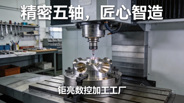
Five-axis machining adds a second rotary axis. The cutter can approach the part from almost any direction in one setup. Long tools reaching into deep pockets can be tilted to a stiffer angle, which reduces chatter and improves the surface finish. Impellers, turbine blades and complex medical implants are the classic cases.
The trade is programming time and machine cost. A five-axis toolpath has to avoid collisions between the holder, the table and the part. That check takes CAM time. If your part has three orthogonal faces and no undercuts, three-axis is the better choice.
- 13-axisPrismatic parts, one or two setups
- 24-axisFeatures on four sides, one setup
- 35-axisUndercuts, contoured surfaces, rigid tool angles
Where CNC Machining Stops Making Sense
CNC is subtractive. Material that is not part of the design becomes chips. On a part machined from a 200 × 200 × 50 mm aluminium billet, most of that billet leaves as swarf. Material cost and cutting time both scale with how much you remove.
Very high volumes are the other boundary. A part needed in 100,000 pieces per year is usually a die casting or a forging with a light machining pass, not a part cut from solid. The machining step still exists, but it shapes a near-net blank rather than the whole geometry.
Very small features hit tool limits. A slot 0.5 mm wide and 6 mm deep needs a cutter with a length-to-diameter ratio of 12:1. That tool deflects. It will chatter, and the wall will not be straight. Redesign the slot wider, or accept a wire EDM step.
Hard materials are not automatically out of reach. Titanium Ti-6Al-4V, 17-4PH stainless and Inconel are machined every day. The cost shows up in tool wear and cycle time, not in feasibility. Expect to pay for the extra time.
- 1High removal volumeMaterial and cycle time both rise
- 2Six-figure volumesCasting plus finish machining is cheaper
- 3Deep narrow slotsTool deflection ruins the wall
Tolerances, Finishes and What They Cost
A general machining tolerance of ±0.1 mm is routine on most metals. Tightening to ±0.005 mm changes the process. You need temperature control, sharp tooling, careful fixturing and more inspection. The part may need to be measured on a CMM rather than with calipers.
Surface finish follows a similar curve. As-machined surfaces sit around Ra 1.6–3.2 μm. A fine finish in the Ra 0.2–0.8 μm range usually needs a finishing pass with a smaller stepover, a sharper insert or a slower feed. That is machine time you pay for.
Not every dimension needs the tight number. Mark only the features that mate, seal or locate. A drawing where every dimension carries ±0.005 mm will be quoted high and machined slowly, for no functional gain.
Inspection closes the loop. A shop that checks only the final part cannot catch a drift that started at part 20. In-process checks on critical features catch the trend before the batch is finished.
- 1Loose±0.1 mm, standard tooling and fixturing
- 2Tight±0.005 mm, CMM verification
- 3Fine finishRa 0.2–0.8 μm, extra finishing pass
Materials, Fixturing and Setup Count
Aluminium 6061 and 7075 cut fast and hold tolerance well. Stainless 304 work-hardens if the feed is too light, so the cutter must stay engaged. Titanium conducts heat poorly, which means the heat goes into the tool edge; coolant delivery matters more than spindle speed.
Fixturing decides whether a tight tolerance is achievable. A part held in a vise on 5 mm of stock will move when the vise is released. Soft jaws machined to the part profile, or a vacuum plate for thin plates, hold the geometry better.
Every setup adds position error. A part machined in one setup from one datum has a much smaller error stack than the same part flipped four times. This is why four-axis and five-axis machines often hit tighter tolerances than a three-axis machine doing the same job.
The number of setups also drives cost. Each one needs a fixture, a probe or an edge finder pass, and an operator decision. Reducing setups is usually cheaper than reducing cycle time.
- 1One setupSmallest error stack, lowest fixturing cost
- 2Soft jawsMatch the part profile, reduce movement
- 3Thin platesVacuum fixturing beats vise clamping
CNC Machining Against Other Processes
Pick by geometry, volume and material, not by habit.
| Process | Best for | Typical lead time | Where it fails |
|---|---|---|---|
| 3-axis CNC | Prismatic parts, tight tolerances | 3–5 days | Undercuts need re-fixturing |
| 5-axis CNC | Contoured and complex geometry | 3–5 days | Higher programming cost |
| Die casting | High volume, simple walls | Tooling weeks | Tooling cost at low volume |
| 3D printing | Early form checks | Days | Weak for load-bearing metal |
| Sheet metal | Flat parts, enclosures | Days | Cannot hold thick bosses |
When CNC Is the Right Answer
If your part is metal or engineering plastic with tight tolerances and a volume under a few thousand pieces, CNC machining is the right process. If the volume is in the tens of thousands and the geometry is simple, cast or forge a near-net blank and machine only the critical faces.
Common Questions
Is a CNC machine the same as a machining center?
A machining center is one type of CNC machine. It has an automatic tool changer and an enclosed work envelope, usually for milling.
A CNC lathe, a CNC grinder, a CNC EDM and a CNC laser are all CNC machines too. The acronym describes the control, not the cutting method.
Do I need G-code knowledge to order machined parts?
No. You need a 3D model or a 2D drawing with tolerances, material and finish called out.
The shop's CAM programmer writes the G-code. If a feature is ambiguous, a short note on the drawing saves a round of questions.
How tight a tolerance can a standard CNC shop hold?
±0.1 mm is routine. ±0.005 mm is achievable on the right machine, in the right material, with the right fixturing and inspection.
Below that, grinding or EDM is usually the better route. Ask which process the shop plans for your critical features.
What is the smallest quantity that makes sense?
One part. CNC has no tooling cost, so a single prototype is economical.
The per-part price drops with volume because setup time is spread across more parts. There is no minimum order quantity to clear.
Can CNC parts be finished after machining?
Yes. Anodizing, plating, powder coating, bead blasting and laser marking are all common next steps.
Tell the shop your finish before machining starts. Anodizing adds a few micrometres per surface, which matters on a threaded or press-fit feature.
How do I know the parts will match the drawing?
Ask what inspection is performed and what report you will receive. 100% inspection before shipment is the baseline for critical parts.
For a first article, request dimensional data on the features you marked as critical.
Send Your Model, Get a Quote and DFM Feedback
Upload a STEP file and we return a quote with a free DFM analysis within 12 hours. No minimum order quantity, and your uploads stay confidential.
12-hour quote±0.005 mm toleranceNo MOQNDA on request
More CNC Process Notes
We publish setup notes, tooling trials and inspection data from the factory floor.











