
What Is a CNC Machine Offset?
A CNC machine offset is the stored distance between the programmed coordinate and the point where the tool actually touches the part. This page explains how offsets work, which types matter on a mill and a lathe, and how to tell when an offset is wrong instead of blaming the program.
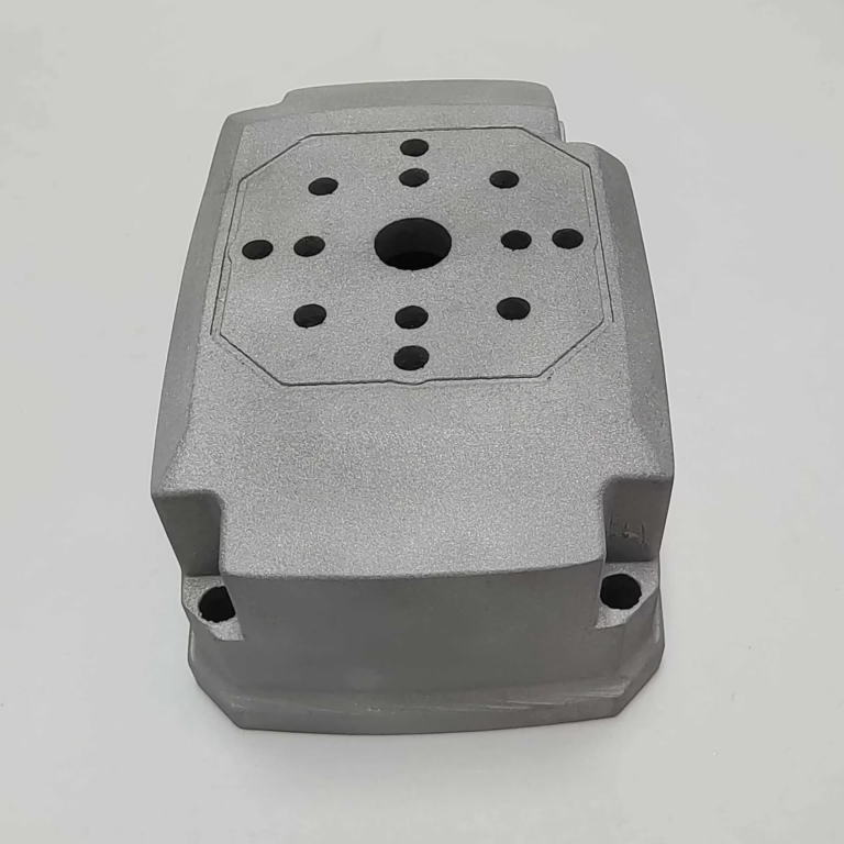
How a cnc machine offset works
A CNC machine offset is a number the control adds to or subtracts from the programmed axis position before it commands the servo. The program says X100.000. The machine cannot move to X100.000 in a useful way until it knows where the part sits and how long the tool is. The offset carries that missing information.
On a mill, the control builds the commanded position from three layers. Machine zero is fixed by the builder and set by homing. Work offset places the part origin in that machine space. Tool length offset adds the distance from the spindle gauge line to the tip of the tool. The sum of those layers is the point the control actually drives to.
On a lathe the same idea appears in different names. Geometry offset holds the theoretical position of the turret station. Wear offset holds the small correction that accumulates after the insert wears or gets replaced. The control adds both before moving. This split matters because geometry should stay stable while wear changes all day.
The offset never touches the part. It only tells the control where the part and tool are. That is why a wrong offset produces a wrong part even when the G-code is perfect, and why a correct offset cannot rescue a program that has the wrong toolpath.
Every offset value is a stored distance in the control, usually in millimeters or inches to four decimal places. When the operator measures a feature and finds it 0.05 mm oversize, the fix is a new number in the table, not a new program.
- 1Machine zeroFixed reference set by homing.
- 2Work offsetPlaces the part origin in machine space.
- 3Tool length offsetSpindle gauge line to tool tip.
- 4Wear offsetSmall correction for tool wear.
The four offset types a machinist actually manages
Work offset, also called fixture offset, is the distance from machine zero to the part zero. On a 3-axis mill you usually set it with an edge finder, a probe, or a dial indicator on a known surface. G54 through G59 are the common registers, and a large machine with many fixtures may use G54.1 P1 through P300. Get this wrong and every feature shifts together.
Tool length offset is the distance from the spindle gauge line to the tool tip. On a machine with a tool presetter you measure offline and type the number in. Without one you touch off each tool on a known surface, or use a spindle probe. A single wrong length offset usually shows up as one tool cutting too deep or not touching at all.
Cutter radius compensation tells the control the radius of the tool so the programmed path can be the part profile instead of the tool centerline. G41 and G42 select left and right. This offset is what lets you adjust a slot width or a pocket wall by changing one number instead of rewriting the path.
Wear offset is the small adjustment that keeps a process in tolerance as the tool degrades. On a lathe it lives in its own column next to geometry. On a mill it may be folded into the length or diameter register, depending on the control. Either way, wear offset is the number you change most often during a run.
A practical rule: geometry and work offsets are setup numbers and should be stable across a run. Wear offsets are running numbers and are expected to move.
- 1Work offsetPart zero in machine space.
- 2Tool length offsetSpindle gauge line to tip.
- 3Cutter radius compensationTool radius for profile paths.
- 4Wear offsetRunning correction for tool wear.
How offsets are set on a real machine
Setting a work offset starts with a clean, known surface. Touch the tool or probe to the face you want as Z0, then to the two edges that define X0 and Y0. Store the values in the active work offset register. If the part is in a vise, indicate the fixed jaw first so the part sits parallel to the axis.
Tool length can be set by touching each tool to a common surface, by using a tool setter on the table, or by measuring offline with a presetter. Offline measurement is faster on a 20-tool job and keeps the spindle free. Touch-off is more accurate on a machine with thermal drift because the measurement happens at the same spindle position used for cutting.
Cutter radius compensation is set from the actual measured tool diameter, not the nominal size. A 10 mm end mill may measure 9.97 mm. If the control uses 10 mm, a pocket that should be 50.00 mm comes out 50.03 mm. Measure the tool, enter the real radius, and let the control do the arithmetic.
Wear offsets are set from inspection data. Measure the first part, compare to the drawing, and move the wear number by the difference. On a lathe turning a Ø25.00 mm shaft that measures 25.04 mm, reduce the X wear offset by 0.04 mm and the next part should land closer. Change one number, cut one part, measure again.
- 1Indicate the viseFixed jaw parallel to the axis.
- 2Measure the toolUse real diameter, not nominal.
- 3Change one numberThen cut and measure again.
Reading offset errors from the part
If every feature on the part is shifted in the same direction by the same amount, the work offset is wrong or the part moved. Check the fixture first, then the work offset register. A part that moved after roughing often shows a shift that grows with depth of cut.
If one tool cuts too deep or leaves stock, the tool length offset for that tool is wrong. The symptom is usually tied to a single tool number. Confirm the tool in the spindle matches the offset number in the program before changing anything. A tool loaded in the wrong pocket produces the same symptom.
If a pocket or slot is consistently oversize or undersize on the walls while depth is correct, look at cutter radius compensation. A wrong radius affects width, not depth. Check the sign and the G41 or G42 direction as well as the value.
If dimensions drift slowly across a run, that is wear, not setup. Trend the inspection data. A gradual change in one dimension points to a wear offset that needs a small correction. A sudden jump points to a tool change, a chip, or a loose insert.
- 1Everything shiftedWork offset or part movement.
- 2One tool offLength offset or wrong pocket.
- 3Width off, depth fineRadius compensation.
- 4Slow driftWear offset correction.
Why offsets decide whether a tolerance is reachable
A tolerance is only as good as the offset that supports it. If the work offset is set to 0.02 mm and the tool length is measured to 0.05 mm, a ±0.005 mm callout is not realistic no matter how rigid the machine is. The offset chain has to be tighter than the tolerance it serves.
Thermal growth is the quiet variable. A spindle that runs for two hours grows, and the tool tip moves with it. On long runs, re-check a known feature every few hours and adjust the wear offset. On a machine with a spindle probe, an in-process check can feed the correction automatically.
Material matters too. Aluminium cuts cool and moves little. Stainless and titanium push heat into the tool and the part, so the same offset that worked on the first part may be off on the tenth. For tight work in those materials, plan a mid-run check.
The practical takeaway is that offsets are not a one-time setup task. They are the loop that keeps the process inside tolerance. Treat them as part of the process, not as paperwork.
- 1Offset chainMust be tighter than the tolerance.
- 2Thermal driftRe-check on long runs.
- 3Material effectHot materials need mid-run checks.
Offset types and what they correct
Use this table to match a symptom to the offset register that needs attention.
| Offset type | Corrects | Typical symptom if wrong | Change frequency |
|---|---|---|---|
| Work offset | Part zero location | Whole part shifted | Setup only |
| Tool length | Tool tip height | One tool too deep or high | Setup or tool change |
| Cutter radius | Tool radius on profile | Walls off, depth fine | Setup or after regrind |
| Wear offset | Slow tool degradation | Dimensions drift over a run | During the run |
| Rotary axis | Angular position of a 4th or 5th axis | Features rotated or indexed wrong | Setup only |
When to correct an offset and when to stop the machine
If one dimension drifts by a few thousandths and the trend is smooth, correct the wear offset and keep cutting. If the shift is sudden, affects several features at once, or follows a fixture change, stop and re-check the work offset and the part clamp before touching any number.
Common questions about cnc machine offset
What is the difference between a work offset and a tool length offset?
A work offset places the part origin in machine space. A tool length offset places the tool tip relative to the spindle gauge line. They are separate registers and both are added to the programmed position.
If the whole part shifts, suspect the work offset. If one tool cuts at the wrong height, suspect the tool length offset.
How often should wear offsets be updated?
On a stable aluminium job, once at the start of a run and again after a few hours is often enough. On stainless or titanium, or on a long unattended run, check the first part and then at fixed intervals.
The right interval is the one that keeps every part inside the tolerance band between checks.
Can a wrong offset be fixed in the program instead?
You can, but it is usually the wrong move. A program edit hides the real error and makes the next setup harder to understand.
Keep geometry and work offsets stable, correct wear in the wear column, and leave the G-code alone unless the toolpath itself is wrong.
Why does a part come out oversize on the walls but correct in depth?
That pattern points to cutter radius compensation. The control is using a radius that does not match the real tool.
Measure the tool, enter the real radius, and check that G41 or G42 is on the correct side of the path.
Do offsets need to be re-set after a tool change?
The length offset does, if the new tool is not identical to the old one. Even a re-ground tool has a different length.
If the machine has a tool setter or a spindle probe, the offset can be measured automatically at the change.
How do offsets fit into inspection and reporting?
Offsets are the link between the setup and the first article. When the first part is measured, any correction goes into an offset, and that correction is part of the process record.
GreatLight inspects 100% of parts before shipment and can supply inspection reports on request.
Need a machined part that holds its tolerance?
Send us your drawing and we will review the offset-critical features, the tolerance chain, and the setup before quoting. Quotation and free DFM analysis within 12 hours.
12-hour quote100% inspectionNo minimum order quantity
More CNC machining notes
We publish setup notes, tooling trials and inspection data from the factory floor.











