
What Is a CNC Plotter Machine?
A CNC plotter machine moves a tool along programmed X and Y axes to cut, crease, or mark flat stock. This page explains the mechanism, the working envelope, and where the tool stops being the right answer. Written for engineers and buyers who need a fit decision, not a brochure.
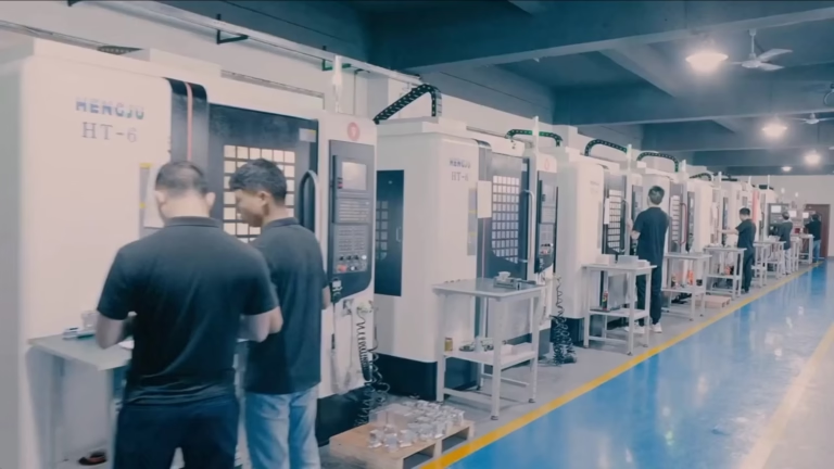
How a CNC Plotter Machine Moves and Cuts
A CNC plotter machine holds a tool in a gantry or a moving head and drives it along X and Y axes under numerical control. The tool is physical: a drag knife, a creasing wheel, a pen, a laser head, or a small router spindle. The machine reads vector data from a design file, breaks each path into line and arc segments, and moves the tool through them. There is no ink and no print head. Material is removed, creased, or marked instead.
The controller does interpolation. For a straight move it simply coordinates the two axis motors; for an arc it computes intermediate points so the tool stays on the true curve within the servo or stepper resolution. That is the same motion core used in a CNC router or mill. What differs is the Z axis. On most plotters Z is a simple up and down signal: tool down to cut, tool up to travel. On 2.5D models the Z axis positions a knife blade or a spindle at several discrete depths, so you can kiss-cut a top layer without cutting the backing underneath.
Tool compensation matters more than most people expect. A drag knife has an offset between the pivot point and the blade tip, so the controller must rotate the head to keep the blade tangent to the path. Without that compensation, corners round off and small radii come out undersized. A laser or spindle tool does not need tangent control, but it does need cutter radius compensation in the CAM step. Either way, the cut path is not the same as the design path.
Backlash, belt stretch, and table flatness set the practical accuracy floor. A well-adjusted belt-driven plotter holds roughly ±0.1 mm on film and paper. A machine with a rigid frame, linear guides, and a vacuum bed can hold much tighter on stiff stock, down to ±0.005 mm on thin metal when the tool is a small spindle rather than a knife. The material, not the controller, is usually the limiting factor.
- 1Vector inputDXF, DWG, or SVG paths, not raster images
- 2Tangent controlRequired for drag knives to cut clean corners
- 3Z signalUp/down on 2D, discrete depth steps on 2.5D
Main Types of CNC Plotter Machine
Cutting plotters are the most common form. A drag knife or a tangential knife follows the path and severs thin material: vinyl, gasket sheet, gasket paper, shim stock, adhesive film, and fabric. They are fast because there is no spindle load, and they waste almost nothing because the tool follows the part outline directly. A gasket cut from a rubber sheet on a cutting plotter can hold ±0.005 mm on the outline when the machine is rigid and the sheet is fixtured flat.
Creasing and scoring plotters replace the knife with a wheel or a blunt stylus. They press a fold line into cardboard, corrugated board, and some plastics so the material bends where you want it to. This is common in packaging prototypes and display work, where a clean fold matters as much as a clean cut.
Pen and marking plotters are the oldest form. A pen or a marker draws the path on paper, film, or coated metal. Engineers use them for layout verification, first-article marking, and inspection templates. Laser marking heads do the same job on metal and anodized surfaces, with a minimum character height around 1.5 mm for legible text.
Router-style plotters add a small spindle to the same X-Y gantry. They cut foam, balsa, acrylic sheet, and thin aluminum, typically to a depth of a few millimeters per pass. They are slower than a knife and leave chips, but they can cut materials a blade cannot and can add a chamfer or a counterbore with the right tool. The trade is speed and fixturing complexity.
- 1KnifeVinyl, gasket, shim, film, fabric
- 2Crease wheelCardboard, corrugated board, folding plastics
- 3Pen or laserLayout marks, inspection templates, labels
- 4Small spindleFoam, acrylic, thin aluminum, 2.5D pockets
Where a CNC Plotter Machine Fits in Part Production
The tool earns its place on flat parts with a constant thickness. Gaskets, shims, insulation washers, membrane switch layers, and adhesive pads are the classic fits. The design is a 2D outline, the material comes in sheets, and the quantity sits between one and a few thousand. Setup is quick because there is no vise, no vise jaw marks, and no chip evacuation to plan. Change the file, change the sheet, run again.
It also fits the front end of a project. A plotter can cut a paper or film template in minutes so you can check a fit against an assembly before anyone cuts metal. That template costs almost nothing and catches interference early. Many shops run a plotter beside a mill for exactly this reason: one machine proves the shape, the other makes the part.
Where it does not fit is anything with real depth. A pocket deeper than a few millimeters, a thread, a bore with a tolerance callout, a contoured surface, or a part that needs to hold a load in three dimensions all belong on a mill or a lathe. A plotter cannot hold a side wall square over 10 mm of depth, and it cannot control a bore diameter to ±0.005 mm the way a boring head can.
Material behavior decides the rest. Soft, gummy plastics smear instead of cutting cleanly, and thin sheets can lift off the bed and tear. A vacuum bed or a tacky mat holds them down. Stiff metal needs a spindle and a rigid frame, which pushes the machine toward router territory. If the sheet is under 0.5 mm and the outline is the only feature, a plotter is usually the faster and cheaper route. If the part has thickness features, it is not a plotter job.
- 1Good fitFlat, constant-thickness parts with 2D outlines
- 2Poor fitPockets, threads, bores, contoured 3D surfaces
- 3WatchGummy plastics and loose thin sheets need hold-down
What Accuracy You Can Realistically Hold
Publishable accuracy depends on three things: the machine frame, the tool, and the material. A light belt-driven plotter on paper holds about ±0.1 mm. Add linear guides, a stiff gantry, and a vacuum bed and the same machine holds ±0.05 mm on film. Switch to a small spindle cutting thin aluminum and the number tightens further, into the ±0.005 mm range for the outline.
The tool sets the edge quality. A drag knife leaves a clean edge on vinyl and gasket sheet but a slightly angled wall, because the blade is a wedge. A laser leaves a heat-affected edge and a small taper. A spindle leaves a machined edge with visible tool marks. If the drawing calls out an edge finish, the tool choice is part of meeting it, not an afterthought.
Repeatability usually beats absolute accuracy on this class of machine. If you run the same file twice on the same sheet, the two outlines land within a few micrometers of each other even if both are offset slightly from the nominal. For gaskets and shims that stack in an assembly, repeatability is what keeps the stack from growing. Absolute position error can be dialed out with one offset; random error cannot.
Thermal drift is real on long runs. A machine that has been running for two hours is warmer than one that just started, and a 1 m long part can move by tens of micrometers on some materials as the sheet and the frame expand. For tight work, run a test coupon at the start of the shift and check it against the drawing before releasing the run.
- 1Paper and filmAround ±0.1 mm on a light machine
- 2Fixtured thin sheetAround ±0.05 mm with a rigid frame
- 3Thin metal, spindleDown to ±0.005 mm on the outline
- 4Long runsCheck a coupon for thermal drift
When to Choose a Plotter and When to Choose a Mill
Choose the plotter when the part is flat, the thickness is fixed, and the only geometry is the outline plus maybe a crease or a mark. This covers gaskets, shims, films, labels, and templates. The cycle time is short, the fixturing is simple, and material waste is low because there is no cutter path clearance to plan around. A hundred-piece run of a rubber gasket is a good day on a plotter and a slow one on a mill.
Choose a mill when the part has depth. A pocket, a step, a thread, a bore, or a face that must be flat within a tolerance all need a rotating cutter and a rigid Z axis. Aluminum, stainless, steel, titanium, and engineering plastics with a 3D shape belong on a 3-axis, 4-axis, or 5-axis machine. The same shop can run both, and often does: the plotter makes the template, the mill makes the metal part.
Choose a laser when the material is thin, the edge can tolerate heat, and you want no tool contact. Lasers cut and mark in one setup, which is useful for labels and serial numbers. They do not cut thick metal, and they leave a heat-affected zone that matters on some alloys. Choose waterjet when the material is thick and heat-sensitive, and you can accept a wider kerf and a slower cycle.
The honest rule is this: if a drawing can be fully described by an outline and a material callout, a plotter is probably the right tool. Add any third dimension with a tolerance, and it is not. That check takes ten seconds and saves a wasted setup.
- 1Plotter2D outline, fixed thickness, one to a few thousand pieces
- 2MillDepth features, threads, bores, contoured surfaces
- 3LaserThin stock, marking plus cutting, heat-tolerant edge
- 4WaterjetThick, heat-sensitive plate with a wider kerf
CNC Plotter Machine vs Other Cutting Methods
Pick the row that matches your part geometry, not the machine you already own.
| Method | Best material | Typical tolerance | Depth features |
|---|---|---|---|
| CNC plotter, knife | Vinyl, gasket sheet, film, shim | ±0.05 to ±0.1 mm | No, through-cut only |
| CNC plotter, spindle | Foam, acrylic, thin aluminum | ±0.005 to ±0.05 mm | Yes, a few mm per pass |
| Laser cutter | Thin steel, acrylic, wood, film | ±0.05 to ±0.1 mm | Limited, taper and HAZ |
| Waterjet | Thick steel, stone, composites | ±0.1 to ±0.2 mm | Yes, with taper |
| 3-axis mill | Aluminum, steel, plastics | ±0.005 mm | Yes, full 3D pockets |
| 5-axis mill | Titanium, Inconel, complex parts | ±0.005 mm | Yes, contoured surfaces |
The Verdict
If your part is a flat outline with a fixed thickness, choose a CNC plotter machine: it is faster, cheaper to set up, and wastes less material. If the drawing has depth, a thread, a bore, or a contoured surface, choose a mill instead and do not try to force the plotter past its envelope.
CNC Plotter Machine Questions
Is a CNC plotter machine the same as a printer?
No. A printer deposits ink on a surface and the result is a graphic. A plotter moves a physical tool that cuts, creases, or marks the material itself. Some plotters do hold a pen, which looks like printing, but the motion system and the tool holder are built for contact work, not for ink delivery.
The practical difference shows up in the output. A printed line has no depth and no edge strength. A plotted cut line separates the part from the sheet, which is why gaskets, shims, and film parts come off a plotter and not a printer.
What tolerance can a CNC plotter machine hold?
On paper and film with a light belt-driven machine, expect around ±0.1 mm. With linear guides, a stiff gantry, and a vacuum bed, film and thin sheet hold near ±0.05 mm. A small spindle cutting thin aluminum can reach ±0.005 mm on the outline.
The material usually sets the floor, not the controller. Soft sheet that stretches, or thin sheet that lifts off the bed, will miss the number even on a good machine.
Can a CNC plotter machine cut metal?
Only thin metal, and only with a spindle rather than a knife. A drag knife will score or tear aluminum foil but will not cut a clean outline in 1 mm sheet. A router-style plotter with a small end mill can cut thin aluminum, brass, and copper in several passes.
For anything thicker than a few millimeters, or for any part that needs a bore or a thread, use a mill. The plotter frame is not built to resist the cutting forces of a heavy pass.
Why do corners come out rounded on a drag-knife plotter?
Because the blade pivots behind the cutting tip, so the head must rotate to keep the blade tangent to the path. If tangent control is off, or the offset value is wrong, the blade lags in corners and the radius grows.
Check the knife offset in the machine settings and run a small test square with a 1 mm corner radius. If the corner measures large, adjust the offset until it matches the drawing.
How do I hold thin sheet down during cutting?
Use a vacuum bed for sheet that covers most of the table, or a tacky mat for small parts. Double-sided tape works for one-offs but leaves residue and slows changeover. For film and paper, a roller feed with a light tension works well.
If the sheet lifts, the cut edge tears and the tolerance is lost. Hold-down is not optional on thin stock. Test the hold on a scrap piece before releasing a production run.
Does a plotter need CAM software?
It needs a toolpath step, but it is lighter than mill CAM. Most plotters accept DXF or SVG directly and apply tool compensation inside the machine controller. You still set cut depth, knife offset, and cut order.
For a spindle plotter, run the same CAM checks you would for a mill: cutter diameter compensation, stepdown, and feed per tooth. The machine is smaller, the rules are the same.
Send Us the Drawing and We Will Tell You Which Process Fits
Upload a DXF or STEP file and our engineers will confirm whether the part belongs on a plotter, a mill, or a laser, with a quotation and DFM notes within 12 hours.
12-hour quoteDFM feedbackNDA on requestNo minimum order
More Process Notes From the Shop Floor
We publish setup notes, tooling trials and inspection data from the factory floor.











