
What Is a Dry Run in CNC Machine Setup?
A dry run in CNC machine work runs the program with no material being cut, so the operator can watch every axis, offset and clearance before the first chip. This page covers how it works, what it can and cannot catch, and when a full dry run is worth the cycle time.
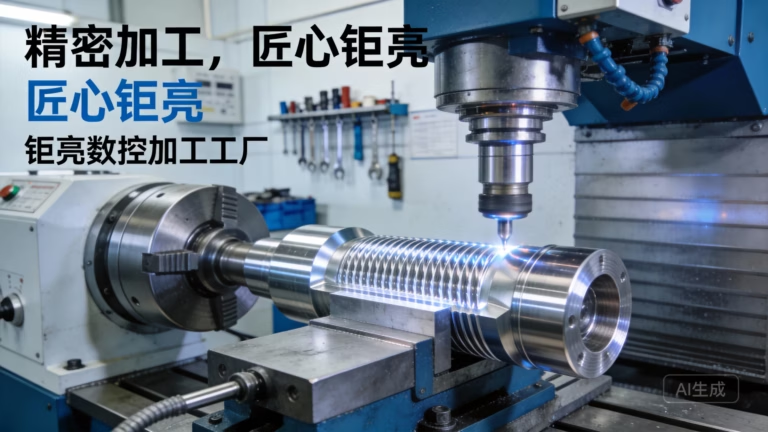
What a dry run in CNC machining actually does
A dry run in CNC machining is a program execution where the machine follows the commanded motion but the tool never touches the workpiece. On most controls you raise the tool offset by a known amount, or you lock the spindle and disable feed into the part, then let the cycle play out. The axes still move, the ATC still changes tools, and the control still reads the same G-code that will cut the part later.
The point is to test the program, not the part. You are checking that rapid moves clear fixtures and clamps, that tool length and work offsets point where you think they point, and that the programmed Z depths sit inside the stock envelope. A crash during the dry run costs a spindle stop and an hour of setup. A crash during a real cut costs a spindle, a holder, and maybe the fixture.
Nothing about the geometry changes during this pass. The control has no idea the tool is offset upward. It simply executes the same block sequence it will execute later, which is exactly why the test is useful. You are validating the instruction stream, not the metal removal.
Keep the distinction clear. A dry run proves motion is where you expect it. It does not prove the part will measure correct. Those are two separate questions, and mixing them up is how people skip the checks that matter.
How to run a dry run in CNC machine control
There are three common ways to run a dry run in CNC machine work, and they differ in how much of the machine actually moves. Pick based on the risk of the job, not on habit.
The first method is the virtual one. CAM software such as Mastercam, NX or Fusion simulates the toolpath in 3D and shows stock removal, holder collisions and gouges. It costs no machine time and catches the majority of programming errors. It cannot catch a wrong work offset on the machine, a clamp that sits 5 mm taller than the model, or a tool loaded into the wrong pocket.
The second method is the physical offset shift. You add a safe value, typically 50 mm to 100 mm, to the tool length offset, then run the program in single block at reduced rapid. The machine moves through every position. Because the tool sits well above the part, a wrong Z depth shows up as an obviously impossible approach rather than a gouge.
The third method locks the spindle and disables the feed override to zero, so only rapid positioning executes. This is fast but tells you nothing about feed-driven motion. Use it as a quick check on a proven program, not on a new one.
On five-axis work the order matters more. Check the rotary table and trunnion clearance first, then the linear moves. A B-axis swing that looks fine in the CAM view can still clip a fixture jaw that was modeled as a simple block.
Faults that show up before the first cut
Most crashes trace back to a small set of mistakes, and nearly all of them surface during a proper dry run. Knowing the list helps you decide how much verification a job needs.
Wrong work offset is the most common. If G54 is set from the wrong corner of the vise, every cut shifts by the same amount, and the dry run shows the tool approaching air where the part should be. Wrong tool length offset follows close behind. A 20 mm difference between the programmed and actual tool shows up immediately as the tool diving toward the table or hovering far above the stock.
Rapid moves into clamps and fixture jaws are the next category. CAM models simplify vises and toe clamps, so the real hardware often sits higher or further into the work envelope. Single-blocking through the rapids at 25 percent feed catches these before contact.
Program structure errors also appear here. A missing G43 after a tool change, a G90 and G91 mix-up, or a subprogram called with the wrong offset will all produce visible nonsense in the motion.
Tool sequence problems round out the list. Duplicate tool numbers in the turret, a chamfer tool called before the roughing tool, or a drill cycle left active into a profile move all announce themselves in the dry run.
What a dry run cannot tell you
No amount of no-cut motion proves the part will meet tolerance. Surface finish, tool deflection, thermal growth and chatter only appear once the tool is in the material. A dry run is a safety check, not a quality check.
Tool wear is invisible until you cut. A 12 mm end mill that has run 40 hours will still trace the right path in the air, then cut undersize or burnish the wall. Check wear before the run, not after the scrap.
Fixtures can move under load. Clamping pressure that deflects a thin wall, or a vise jaw that lifts slightly when the cut loads it, will not show up in an unloaded pass. For thin-wall parts, plan a lighter first cut rather than trusting the dry run.
Material behavior stays unknown until contact. Aluminum 6061 at 3,000 rpm sounds and cuts differently from Ti-6Al-4V at 400 rpm. The dry run cannot warn you about a speed and feed choice that will snap a tool.
When to dry run and when to skip it
Running every job the same way wastes machine time. Running none of them risks the spindle. The useful rule is to dry run anything where the cost of a crash is higher than the cost of the verification pass.
Run a full dry run for a first article, a new fixture, a first five-axis setup, or any part with a deep pocket, long tool reach or a tight envelope. These are the cases where a single wrong number costs more than an hour of spindle time.
Skip the physical move on proven repeat work. If the same program has run 40 times on the same fixture with the same tooling, a simulation pass and a first-piece inspection cover it. Re-verify only when something changes, such as a new tool holder, a re-clamped vise, or a revised program.
Use the machine's own tools for this. Most controls offer graphics simulation, and many offer a trace or verification mode that draws the path on screen. Combined with a first-piece check on a ±0.005 mm part, that covers the realistic failure modes without burning a full cycle.
At GreatLight we run this check as a standard step on new setups across 127 high-precision CNC machines, including 16 simultaneous 5-axis centers. It is one reason the qualification rate on released parts sits at 99.99 percent.
Dry run methods compared
Choose by risk level and machine availability, not by convenience.
| Method | What moves | Catches | Best for |
|---|---|---|---|
| CAM simulation | Nothing on the machine | Toolpath, holder, gouge errors | Every new program, first pass |
| Offset shift +50–100 mm | All axes, tool high above part | Wrong Z depth, offsets, rapids | First run of a new setup |
| Single block at 25% rapid | All axes, full program | Clamp and fixture clearance | High-risk or tight fixtures |
| Spindle lock, rapid only | Rapids and tool changes | Tool sequence, wrong pockets | Repeat jobs, proven programs |
The call
If a job is new, tight, or expensive, run the physical dry run with the tool offset up 50 mm and single block through the rapids. If the program and fixture have already proven themselves, stick to CAM simulation plus a first-piece inspection.
Common questions
Does a dry run wear out the machine?
It puts cycles on the axes, ballscrews and tool changer, so it is not free. On a new program that is a good trade. On a job that has run clean 50 times, the wear adds up without adding much information.
Keep the pass short: rapid-only mode where possible, and skip the full program when simulation already covered the toolpath.
Can I dry run with the tool offset raised instead of removing the workpiece?
Yes, and this is the most common shop method. Add 50 mm to 100 mm to the tool length offset, run in single block at 25 percent rapid, and watch each approach.
Remember to restore the offset before the real cut. A forgotten reset is one of the few ways a dry run itself causes a crash.
Is a dry run required by ISO 9001 or IATF 16949?
Neither standard names a dry run as a required step. Both require documented control of the process so that nonconforming work is prevented.
Most shops satisfy that with a first-article inspection plan plus a verification step for new setups. The dry run is one way to implement it, not the only way.
How long should a dry run take?
A rapid-only pass on a typical 3-axis job takes two to five minutes. A full single-block pass on a complex 5-axis part with long tool reach can take 30 minutes or more.
That is still far cheaper than a broken holder, a scrapped forging or a missed delivery date.
What is the difference between a dry run and an air cut?
In a dry run the tool does not touch material at all, so nothing is removed. In an air cut the tool runs at full programmed speed and feed but in empty space, usually just above the stock.
The air cut tests spindle speed, feed rates and chip evacuation without cutting. The dry run tests motion and offsets. They answer different questions.
Can a dry run catch a collision between the holder and the fixture?
Only if the simulation model includes the real holder geometry and the real fixture. A generic holder model will miss a long-nose holder that reaches further than expected.
Measure the actual tool assembly and update the CAM model. That single step removes most of the remaining collision risk.
Send us the drawing and the setup
We review the program and the fixture plan before the first cut, and we quote within 12 hours with a free DFM analysis.
12-hour quote100% inspectionNo minimum order quantity
More CNC process notes
We publish setup notes, tooling trials and inspection data from the factory floor.











