
What Is Feed Rate in a CNC Machine?
In cnc machine programming, the feed rate is the speed at which the cutter travels along its path, measured in mm/min or IPM. This page explains how it is calculated, how it differs from cutting speed, and when a value that looks correct in the CAM file still produces scrap.
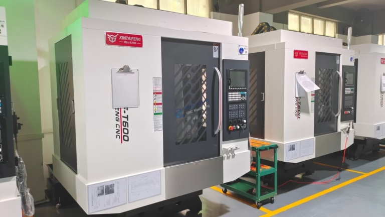
In CNC Machine Work, Feed Rate Means Distance per Minute
On a CNC machine, the feed rate is the linear speed of the cutting tool relative to the workpiece while it is engaged in the cut. On a mill it is usually written as mm/min or inches per minute (IPM). On a lathe the same motion is called feed per revolution, written mm/rev or in/rev, because the tool advances once per spindle turn rather than continuously.
This value only applies during cutting moves. Rapid moves, tool changes and dwell commands are separate motions and should never be mixed into a feed calculation. A program can show a feed of 1,200 mm/min on the screen while the tool is actually cutting at a different effective speed, because the controller slows down at corners and short arc segments.
The number is not a preference or a machine setting. It is a physical rate that determines how thick a chip each tooth removes, how much heat enters the tool, and how hard the machine pushes against the part. Get it wrong in either direction and the result shows up as poor finish, broken tools or a dimension that will not hold.
- 1MillLinear travel of the cutter, mm/min or IPM
- 2LatheAdvance per spindle revolution, mm/rev or in/rev
- 3Cutting moves onlyRapids and dwells sit outside the value
Cutting Speed vs Feed Rate: Two Different Controls
Cutting speed is how fast the cutting edge moves through the material at the point of contact. It is expressed in surface feet per minute (SFM) or meters per minute (m/min) and it is set by spindle RPM and tool diameter. Feed is the other axis of the same motion: how far the tool travels per tooth or per revolution.
Engineers confuse the two because both are written as speeds. Changing RPM changes cutting speed and also changes chip load if the feed stays fixed, so the two cannot be tuned independently without thought. A 12 mm carbide end mill at 8,000 RPM in 6061 aluminium runs near 300 m/min surface speed, which is normal for that alloy. Push the same RPM on 316 stainless and the edge will burn within a minute.
The practical split is this: cutting speed controls tool life and heat, feed rate controls chip thickness and the mechanical load. When a tool wears too fast, look at surface speed first. When a tool chips, chatters or leaves a bad floor finish, look at feed and chip load first.
- 1Cutting speedEdge velocity at contact, SFM or m/min
- 2Feed rateTravel along the path, mm/min or mm/rev
- 3Both move togetherRPM changes chip load if feed is fixed
How to Calculate Feed Rate from Chip Load
The standard formula for milling connects feed, spindle speed, tooth count and chip load: feed rate (mm/min) = RPM × number of teeth × chip load per tooth (mm). The chip load comes from the tool supplier's data for a given material, and it is the number the whole calculation rests on. Everything else is arithmetic.
Take a 10 mm three-flute carbide end mill in 6061-T6 at 7,500 RPM with a recommended chip load of 0.05 mm per tooth. Feed = 7,500 × 3 × 0.05 = 1,125 mm/min. That is the programmed value for a full-width slot. For a light finishing pass with 0.3 mm radial engagement, the same tool can often run 30 to 50 percent faster without overloading the edge, because the chip thins as radial engagement drops.
Turning uses a shorter formula: feed per revolution comes straight from the insert grade chart, and feed rate = feed per rev × RPM. A 0.25 mm/rev feed at 1,200 RPM gives 300 mm/min of linear travel. On lathes the chip load is the same as the feed per rev, so there is no tooth count to multiply.
These formulas assume the machine can actually reach the commanded value. Acceleration limits, look-ahead and corner deceleration all reduce the real average feed on complex 3D surfaces. On a mold cavity with thousands of short segments, programmed feed of 2,000 mm/min may average 1,100 mm/min in the cut.
- 1MillingFeed = RPM × flutes × chip load per tooth
- 2TurningFeed = feed per rev × RPM
- 3Chip thinningLight radial cuts allow higher feed
What Drives the Right Value for Your Part
Material sets the starting window. Aluminium 6061 and 7075 tolerate high surface speed and generous chip loads. Stainless 304, 316L and 17-4PH work-harden, so the tool must keep moving and cut under the hardened layer instead of rubbing on it. Titanium Ti-6Al-4V and Inconel sit at the other end: low surface speed, moderate chip load, flood coolant and no dwelling in the cut.
Tool geometry and coating decide how much of that window you can use. A three-flute aluminium-specific cutter with polished flutes evacuates chips fast. A variable-helix cutter for steel reduces chatter at high axial depth. Coating matters too: TiAlN for dry or high-temperature steel work, diamond-like coatings for abrasive composites, uncoated polished carbide for aluminium to avoid built-up edge.
Machine rigidity and fixturing are the real ceiling. A 4,000 mm gantry machine and a 500 × 500 × 450 mm compact VMC will not hold the same feed on the same tool, because deflection scales with overhang and spindle stiffness. Thin-walled parts are the hardest case: the workpiece deflects, so the effective chip load drops and the tool rubs instead of cutting.
For finishing passes on tight-tolerance features, the target is usually Ra 0.8–1.6 μm or finer, and feed per tooth is the main lever. Too low and the tool burnishes the surface; too high and the scallop height between passes shows up on the inspection report. A 0.02 to 0.04 mm chip load with a 0.2 to 0.3 mm stepover is a common finishing range for aluminium and mild steel.
- 1AluminiumHigh surface speed, high chip load, polished flutes
- 2Stainless and PH gradesKeep cutting, avoid dwelling and work hardening
- 3Titanium and InconelLow surface speed, coolant, rigid setup
- 4Thin wallsReduce radial engagement before reducing feed
Where a Correct Feed Rate Still Fails
A value that is right on paper can still fail in the cut. The most common reason is tool overhang. A 6 mm end mill hanging 60 mm out of the holder deflects under normal cutting force, so the actual chip load at the tip differs from the commanded value and the wall comes out tapered. Shorten the overhang or reduce the axial depth before changing feed.
Corner deceleration is the second cause. Controllers slow the tool to maintain accuracy through tight radii, but the programmed feed stays on the screen. The result is a rub in the corner, a shiny patch and accelerated wear on one flute. High-speed machining toolpaths spread the load instead of forcing the machine to stop and restart.
Chip evacuation limits feed in deep pockets. If chips recut, the effective load rises and the edge chips. Air blast, through-tool coolant or a larger radial stepover that throws chips clear all matter more than the feed number itself. On plastics such as POM and PEEK, feed that is too low generates heat and melts the surface, so the fix is often a higher feed with a sharp uncoated tool.
Finally, thermal drift changes dimensions over a long run. A spindle that has run for hours sits at a different temperature than one that just started, and the tool grows. On work held to ±0.005 mm, that shift can consume the whole tolerance band. Warm-up cycles and in-process checks are part of holding the number, not extras.
- 1Long overhangDeflection changes the real chip load
- 2Tight cornersController slows below the programmed feed
- 3Poor chip evacuationRecut chips chip the edge
- 4Thermal growthWarm-up and in-process checks hold tolerance
Which Parameter to Adjust First
Match the symptom to the control that fixes it before touching the program.
| Symptom | Adjust first | Typical direction |
|---|---|---|
| Edge wears or discolors fast | Cutting speed | Lower RPM or pick a coated grade |
| Tool chipping at entry | Feed per tooth | Reduce chip load, check runout |
| Chatter on thin walls | Feed and radial depth | Lower radial engagement, keep chip load |
| Floor finish looks smeared | Feed per tooth | Raise chip load above rubbing range |
| Burr on 304 stainless | Feed per tooth | Increase chip load, sharpen geometry |
| Dimension drifts on deep pocket | Feed and tool deflection | Shorter tool, lighter stepover |
Set Feed from Chip Load, Not from the Screen
Start with the tool supplier's chip load for the material, calculate feed from RPM and flute count, then trim it for rigidity, engagement and chip evacuation. If surface finish or tool life is the problem, adjust cutting speed first. If the tool chips, chatters or the dimension drifts, adjust feed and engagement. When your parts run to ±0.005 mm and Ra 0.8–1.6 μm, send the drawing and we will set the parameters on the machine, not in a spreadsheet.
Frequently Asked Questions
Is feed rate the same as cutting speed?
No. Cutting speed is the velocity of the cutting edge at the point of contact, written in SFM or m/min and set by RPM and tool diameter. Feed rate is the distance the tool travels along the path, written in mm/min or mm/rev.
They interact. If you change RPM and leave feed alone, chip load changes with it, so the two are tuned together rather than separately.
What units are used for feed rate?
Milling programs use mm/min or inches per minute (IPM). Turning programs use feed per revolution, mm/rev or in/rev, because the reference is one spindle turn.
Some controllers accept feed per tooth as well. Check the machine manual before switching units mid-program.
Can a feed rate be too low?
Yes. If the chip load falls below the edge radius of the tool, the cutter rubs instead of shearing. That raises heat, work-hardens stainless, smears aluminium and shortens tool life.
The symptom is a shiny, burnished surface and poor dimensional control. Raise the chip load or reduce the radial engagement to thin the chip while keeping the edge engaged.
How do you calculate feed rate for a specific material?
Start from the tool supplier's recommended chip load for that material and tool diameter. Then apply feed = RPM × number of flutes × chip load per tooth.
Verify with a test cut. Measure the chip thickness, listen for chatter and check the surface. The formula gives the starting point; the machine tells you whether it holds.
Does feed rate affect surface finish?
It is the main lever on finish. Higher feed per tooth increases scallop height between passes and leaves visible marks. Lower feed can burnish or rub the surface.
For finishes down to Ra 0.8–1.6 μm, use a moderate chip load with a small stepover and a sharp tool, and keep the tool path engaged rather than letting it dwell.
What happens if the feed rate is too high?
Cutting force rises with chip load, so the tool deflects or breaks. On thin walls the part itself deflects, and the dimension goes out of tolerance before anything visibly fails.
Watch for chatter marks, discolored chips and a sudden change in spindle load. Back off the chip load and check runout before restarting.
Send Your Drawing, Get the Parameters Right
Tell us the material, tolerance and quantity. We will confirm the tooling and cutting parameters and quote within 12 hours, with production able to start within 24 hours.
12-hour quote100% inspectionNo minimum order quantityNDA on request
More Machining Notes
We publish setup notes, tooling trials and inspection data from the factory floor.











