
What Is Kerf in a CNC Machine?
Kerf in a CNC machine is the width of material your cutter removes on each pass. It sets the real size of a slot, the leftover stock on a wall, and the offset your CAM file must carry. This page explains where kerf comes from, when it matters, and when you can ignore it.
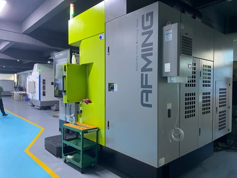
How kerf in cnc machine work is measured
Kerf is the width of the cut. When a Ø10 mm end mill travels through aluminium, it leaves a slot about 10 mm wide. That slot is the kerf. It is not a defect and not a setting you can switch off. Every cutting process removes material, and the removed band has a width.
On a milling machine the kerf in a CNC machine is close to the cutter diameter plus a small amount of tool runout. A 12 mm three-flute cutter with 0.02 mm runout cuts about 12.04 mm. On a laser or waterjet the kerf is much narrower, often 0.1–0.5 mm, but it still changes the final outline.
The workpiece does not push back. The cutter removes whatever sits inside its swept circle. That is why the nominal diameter on the tool holder label is the first number a programmer needs, and why a used cutter measures smaller than its marked size.
Measure kerf the same way you measure any feature: cut a test slot in the same material, then check it with a caliper or a pin gauge. Do that once per tool and per material, and you stop guessing.
- 1New carbide cutterKerf matches the marked diameter within a few micrometres.
- 2Worn cutterDiameter drops, so the slot narrows and the wall grows.
- 3Laser or waterjetKerf is 0.1–0.5 mm and varies with power, speed, and focus.
Why kerf in a CNC machine is built into the tool path
A CAM tool path is written for the centre of the cutter, not for the edge. If the control drove the centre along the part outline, every wall would sit one tool radius away from where the drawing says. The part would come out undersized by the full cutter diameter on both sides.
Cutter compensation fixes that. The programmer enters the kerf value, and the control shifts the path sideways so the cutting edge, not the centre, touches the finished surface. On a Fanuc-style control this is G41 for a left offset and G42 for a right offset, cancelled with G40.
The offset direction depends on travel direction and on whether you are cutting a pocket or a boss. Get it backwards and the cutter eats into the part instead of leaving stock. That mistake shows up on the first article, not on the drawing.
Modern CAM software applies the offset automatically from the tool library. The library entry is only as good as the diameter you typed in. If the library says 6.00 mm and the actual cutter measures 5.94 mm, the finished wall drifts by 0.03 mm.
- 1G41Cutter offset to the left of the travel direction.
- 2G42Cutter offset to the right of the travel direction.
- 3G40Cancel compensation before the next move.
Where kerf in a CNC machine decides the part
Internal corners are the clearest case. If a pocket has a 5 mm corner radius and you rough it with a Ø12 mm cutter, the tool cannot reach the corner. You need a smaller cutter, or you accept a larger radius. The kerf and the corner radius are tied together.
Thin walls are the second case. A 0.8 mm aluminium wall cut with a Ø6 mm cutter carries a lot of radial force. The wall can deflect, and the finished thickness varies along the length. Rough with a larger cutter, then finish with a light radial pass.
Slot width is the third. A slot cut with a single pass is exactly one kerf wide. If the drawing calls for a 6.00 mm slot and your cutter cuts 6.04 mm, the slot is out of tolerance before you start. Two passes with a smaller cutter give you control.
For parts with a tolerance of ±0.005 mm, we measure the cutter, record the actual diameter, and let the CAM offset carry that number. The kerf value in the program is a measured value, not a catalogue value.
On sheet processes the same logic applies. Laser and waterjet kerf is narrow, but it still has to be added to the nest. If you ignore it, the cut part is smaller than the drawing and the holes sit in the wrong place.
- 1Internal cornerSmallest reachable radius equals the cutter radius.
- 2Thin wallUse light radial passes to limit deflection.
- 3Tight slotCut in two passes to control the final width.
What pushes the real kerf off the nominal value
Tool runout is the biggest single factor. If the cutter sits 0.02 mm off the spindle axis, one flute does most of the cutting and the effective diameter grows. On a finishing pass that runout goes straight into the wall position.
Deflection is next. A long, slender cutter bends under cutting force, so the bottom of the slot is narrower than the top. Depth of cut and feed rate decide how much. Keep the radial engagement low when the wall matters.
Thermal growth matters on long cuts. A spindle and a workpiece both expand as they warm up. A machine that cuts a good first article at 08:00 can drift by a few micrometres by 14:00 on a long run. Warm up the spindle before the first cut.
Tool wear closes the diameter over time. A cutter that measures 6.00 mm at the start of a batch may measure 5.97 mm at the end. For long runs, schedule a mid-batch check of the finished wall, not just the first part.
All of these factors are small on their own. Together they explain why the kerf value in the program should be a measured number from the actual setup.
- 1RunoutRaises the effective diameter and shifts the wall.
- 2DeflectionMakes the slot narrower at the bottom.
- 3WearShrinks the diameter across a long batch.
How kerf differs across cutting processes
Milling kerf tracks the cutter diameter. A Ø8 mm cutter gives roughly an 8 mm kerf, and you can change it by changing the tool. That flexibility is why milling suits pockets, slots, and contoured walls.
Laser kerf is narrow and fixed by the beam, not by a tool you can swap. On thin sheet the kerf may be 0.15 mm; on 6 mm steel it can reach 0.4 mm. The kerf also changes with assist gas and focus position, so the nest offset must match the cutting recipe.
Waterjet kerf is wider than laser and tapers through the thickness. A typical value is 0.6–1.2 mm, wider at the bottom of the cut. For a part with a tight tolerance on the outline, that taper has to be planned into the offset.
Plasma kerf is the widest of the sheet processes and leaves a rougher edge. It suits structural plate where a 1–2 mm edge variation is acceptable, not a mating face.
The engineering point is simple. Kerf is not one number you learn once. It belongs to the process, the tool, and the material in front of you.
- 1MillingKerf equals cutter diameter; you choose it.
- 2LaserNarrow kerf, fixed by beam and recipe.
- 3WaterjetWider kerf with a taper through the thickness.
Kerf by cutting process
Typical values; check the actual recipe for your material.
| Process | Typical kerf | Controlled by | Best for |
|---|---|---|---|
| End milling | Equal to cutter diameter | Tool choice and offset | Pockets, slots, contoured walls |
| Laser | 0.1–0.4 mm | Beam, gas, focus | Thin sheet with fine detail |
| Waterjet | 0.6–1.2 mm | Orifice and abrasive flow | Thick plate, no heat input |
| Plasma | 1–2 mm | Nozzle and current | Structural plate, rough edge |
| Wire EDM | 0.2–0.3 mm | Wire diameter and offset | Hardened steel, sharp corners |
When kerf changes your process choice
If the slot or wall tolerance is tighter than the natural kerf variation, choose a smaller cutter and take two passes. If the outline is loose and the material is thin sheet, laser or waterjet kerf is easier to live with than milling.
Frequently asked questions
Is kerf the same as tool diameter?
On a milling machine it is close but not identical. The slot measures slightly more than the marked diameter because of runout and cutting force.
For rough numbers, use the diameter. For a tolerance of ±0.005 mm, measure the actual cutter and use that value.
Does kerf matter on a finishing pass?
Yes. The finishing pass sets the final wall position. If the offset is wrong, the wall moves by the error, no matter how good the surface finish looks.
This is why we check the cutter diameter before the finishing pass on tight parts.
Can I reduce kerf on a laser?
To a point. A shorter focal length and a smaller nozzle give a narrower kerf, but they also reduce the practical cutting thickness.
The kerf you get is a balance between edge quality, speed, and material thickness.
How do I measure kerf in my shop?
Cut a short slot in the same material with the same tool and parameters. Measure the slot width with a caliper or a pin gauge.
Record the number per tool and per material. Update it when you change the cutter.
Does cutter compensation fix a wrong kerf value?
No. Compensation moves the path by the value you enter. If that value is wrong, the finished size is wrong.
Compensation is only as good as the measured kerf in the tool library.
Send your drawing and get a machinability check
We review wall thickness, corner radii, and slot widths against the kerf of the process we plan to use. Quotation and free DFM analysis within 12 hours.
12-hour quote100% inspectionNo minimum order
More machining notes
We publish setup notes, tooling trials and inspection data from the factory floor.











