
What Is Live Tooling on a CNC Machine?
Live tooling puts a driven, motorized tool in the turret of a lathe or the spindle head of a mill. The tool spins on its own axis while the part stays clamped in one position. This guide explains the mechanism, the axes involved, and when a single-setup workflow beats moving the part to a second machine.
In this article
- 1
- 2
- 3
- 4
- 5
- 6
- 7
Key takeaways
How live tooling on a CNC machine actually works
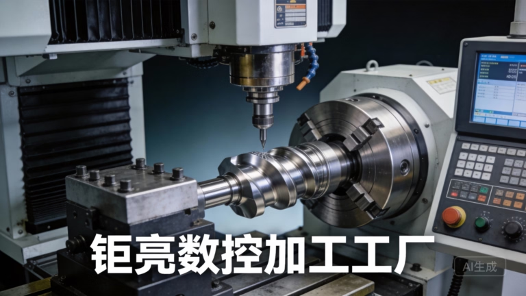
A standard CNC lathe spins the workpiece and pushes a fixed cutting tool into it. The tool never rotates on its own. Live tooling changes that: selected positions in the turret hold powered tool holders, each with a small motor and a drive shaft. When the controller calls that station, the tool spins at its own speed while the spindle holds the part at a fixed index angle.
That combination is the whole trick. The part can be turned like normal, then indexed to 0°, 90° or any angle, and a rotating end mill or drill can cut a cross hole, a flat or a slot. No second machine, no re-fixturing, no re-datum. On a mill, the same idea appears as a driven spindle that tilts and rotates around extra axes, which is how 5-axis work reaches features on the underside of a part.
The controller has to sync two motions at once: the rotary position of the part and the feed of the driven tool. On mill-turn centers this is handled by the same control loop that runs the C-axis. Get the sync right and you hold position within ±0.005 mm. Get it wrong and cross holes drift out of angular tolerance, which is the most common failure mode on a driven turret.
- 1Driven holderA turret station with its own motor and gear or belt drive.
- 2C-axisThe spindle's controlled rotary axis, used to index the part to an angle.
- 3Y-axisOptional linear offset that lets an end mill cut off-center without a special holder.
Live tooling on lathes vs mills
On a lathe, live tooling lives in the turret. A 12-station turret might carry four or six driven stations and the rest static. Those driven stations handle cross drilling, axial drilling on the part face, milling a hex or a flat, and rigid tapping. The part never leaves the chuck, so concentricity between the turned diameter and the cross feature stays tight.
On a mill, the term usually describes a spindle that can drive a tool around additional rotary axes. A 5-axis machining center tilts the tool or the table so the cutter approaches from an angle instead of straight down. That is how you machine a turbine blade root or a bone plate with undercuts that a 3-axis machine simply cannot reach.
The two are not the same capability. A lathe with live tooling is still fundamentally a turning machine that can mill a little. A 5-axis mill is a milling machine that can reach almost any angle but does not turn a diameter in one continuous pass. Choosing between them comes down to which feature dominates the part.
The drive systems behind a live tool
Most driven holders use a belt or gear train from a motor mounted in the turret body. Belt drives run quieter and absorb some shock, but they stretch over time and need tension checks. Gear drives hold timing better and handle higher torque, which matters when you tap M8 or larger in stainless. Either way, the holder's max speed is usually well below the main spindle, often 4,000 to 6,000 rpm.
That speed ceiling shapes the cutting data. You cannot run a 10 mm end mill in aluminum at the same surface speed you would use on a 5-axis mill. Feed per tooth has to drop, and radial engagement has to stay conservative because the holder is less rigid than a spindle taper. Tool runout also matters more: 0.01 mm of runout on a driven holder will show up as a size drift on a cross hole.
Some machines use a Y-axis instead of special holders to cut off-center. With Y-axis travel, a standard end mill can mill a flat anywhere across the part face. That is often more flexible than swapping in an offset holder, and it removes a setup step. The trade-off is machine cost and a slightly larger footprint.
Boundary conditions engineers should check first
Live tooling does not remove the need for a second operation in every case. If a feature sits on a face the turret cannot reach, or if the part is too long to swing with the turret at that angle, you still need a separate setup. Long shafts are the classic example: the driven tool may not clear the steady rest or the tailstock.
Rigidity is the other limit. A driven holder hangs out further than a static turning tool, so chatter risk goes up on interrupted cuts or hard materials. Titanium and Inconel often need reduced depth of cut and more passes. On plastics, the concern flips: the tool can grab and melt the material if feed is too light.
Angular tolerance is the third check. If a cross hole has to sit within ±0.5° of a datum, the C-axis resolution and the holder's repeatability both matter. Ask for the machine's index accuracy before you commit a tight angular callout. A feature that looks simple on the drawing can be the one that drives the whole process plan.
How a live tooling job runs at GreatLight
- 11. Review the drawingWe check which features need driven tools, what angular tolerance applies, and whether a Y-axis or a special holder fits best.
- 22. Pick the machineMill-turn centers handle parts up to Ø400 mm on the rotary table. Larger work moves to a 5-axis center with 4,000 mm travel.
- 33. Set the datumThe C-axis zero is established against the turned diameter so cross features stay concentric to the OD.
- 44. Cut the turning passOD and face turning run first at normal parameters, typically Ra 0.8–1.6 μm as machined.
- 55. Index and millThe spindle indexes, the driven tool engages, and cross holes, flats or slots are cut in the same clamping.
- 66. Inspect in processAngular position and hole size are checked before the part leaves the chuck, not after.
When live tooling pays off and when it does not
Match the part geometry to the setup.
| Part feature | Live tooling | Static tooling | Why |
|---|---|---|---|
| Cross hole in a shaft | One setup | Two setups | Angular position held by C-axis index |
| Flat on a turned OD | One setup | Mill after turning | No re-datum between operations |
| Simple round bushing | Little gain | Faster | No cross features to machine |
| Hex on a fitting | One setup | Second op | Indexed milling replaces a separate mill |
| Deep axial bore | Limited | Preferred | Turning tools reach depth more rigidly |
| Undercut on a profile | Angle access | Cannot reach | Requires a tilting spindle or table |
The short answer
If the part is round with cross features, live tooling on a CNC machine saves a setup and protects angular position. If it is a simple turned profile with no off-axis work, a static turret is faster and cheaper.
Live tooling questions we hear from engineers
Is live tooling only found on CNC lathes?
No. On lathes it means driven holders in the turret. On mills and 5-axis machines the same principle appears as a spindle that rotates the tool around extra axes so it can approach the part from an angle.
The underlying idea is the same: the tool moves on its own axis while the part is positioned by a controlled rotary axis.
Does live tooling improve part precision?
It improves position, not surface finish on the turned diameter. Because cross features are cut in the same clamping as the OD, concentricity and angular position stay tight, often within ±0.005 mm.
Surface finish on the turned portion still depends on the turning parameters, not on the driven tool.
Can live tooling cut both metal and plastic?
Yes. Aluminum, stainless, steel, titanium and engineering plastics such as POM, PEEK and PC all run on driven holders.
The parameters change. Plastics need higher feed and sharp tooling to avoid melting. Titanium needs lower depth of cut because the holder is less rigid than a spindle taper.
What is the difference between live and static tooling?
A static tool is locked in the holder and only moves along the machine axes. A live tool has its own motor and rotates, so it can mill, drill and tap.
A static turret can only turn. That is the practical distinction that decides the process plan.
Can live tooling run low-volume prototype work?
Yes, and that is often where it pays off most. One setup means fewer fixtures and less programming time before the first part is cut.
At GreatLight there is no minimum order quantity, so a single prototype and a 10,000-part run both go through the same driven-tool workflow.
Send us the drawing and we will tell you if live tooling fits
We review the geometry, flag which features need a driven tool, and send a quotation with free DFM analysis within 12 hours.
12-hour quote±0.005 mm tolerance100% inspection
More machining notes
We publish setup notes, tooling trials and inspection data from the factory floor.











