
What Is Plug and Milling? The Basics and Where It Fits
Plug and milling is the shop-floor name for plunge milling: the cutter feeds straight down the Z axis, then steps over, instead of sweeping sideways. This page covers how the cut loads the tool, when it beats side milling, and the geometry that rules it out. Written for engineers and buyers who need to pick a strategy, not a slogan.
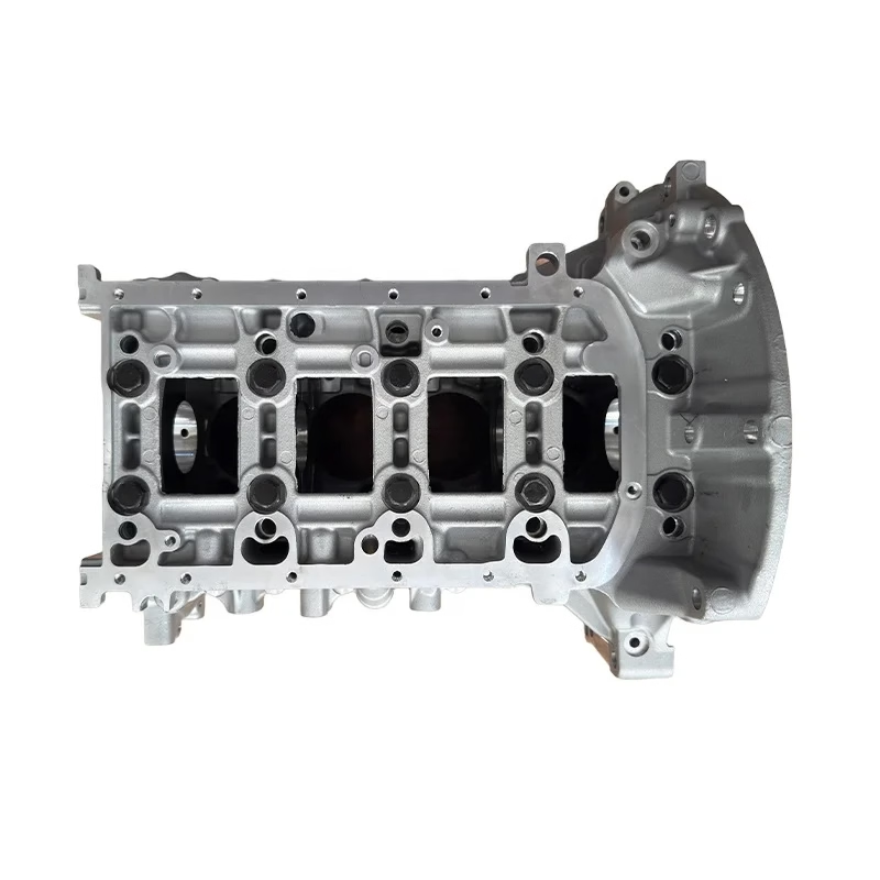
How plug and milling removes metal
In a standard side milling pass, the cutter moves in X or Y and engages the material along its flank. The flute touches the wall over a long arc, and the chip thins toward the end of the cut. That is efficient on shallow walls, and inefficient on deep ones.
A plunge cut works the other way. The tool axis points along Z, the feed goes straight down, and each flute bites a chip that starts thick at the tip and thins as the insert rotates out of the cut. The radial engagement stays small, so the cutting force pushes up the spindle axis instead of bending the tool sideways.
That single change fixes the biggest problem in deep cavities. A long, slender cutter in a deep pocket has very little resistance to side load. Bending grows with the cube of the length-to-diameter ratio, so a 20 mm cutter hanging 100 mm out of the holder deflects far more than a 10 mm overhang. Feeding down Z barely bends it at all.
The cut is still interrupted. Every insert enters and exits once per revolution, which puts a cyclic load on the edge and the spindle bearing. On tough stainless or titanium this shows up as chatter and edge chipping if the feed per tooth is too low. The insert rubs instead of cutting, work-hardens the surface, and the next pass hits a harder skin.
- 1Load directionAxial in plunge milling, radial in side milling. Axial load is what a spindle takes best.
- 2Chip shapeShort and thick, so it clears the pocket without recutting.
- 3Weak pointThe bottom of the hole, where the tool tip contacts a near-flat surface.
Tool geometry that makes plunge milling work
Plunge milling is normally done with a purpose-built tool, not a general-purpose end mill. The inserts sit on the end face, the body is short and stiff, and the diameter is small relative to the shank. A 25 mm plunge cutter on a 32 mm shank is a common pairing for cavities 150 mm deep.
Insert geometry matters more than the body. A positive rake and a sharp edge reduce the axial thrust needed to start the cut. On aluminum, 2 or 3 inserts with polished flutes keep the chip from welding to the face. On 4140 or 17-4PH, a negative rake with a strong edge holds up better but raises the thrust by 15 to 25 percent.
Coolant has to reach the tip. Through-spindle coolant at 40 to 70 bar is the usual answer. Without it, chips pack at the bottom of the hole and the cutter recuts them, which doubles the load on the edge in a few seconds. If through-coolant is not available, an air blast plus a retract cycle every 3 to 5 mm of depth is the next best option.
The tool must be held short. Every millimeter of gauge length added to the holder costs stiffness. A shrink-fit holder or a hydraulic chuck beats a collet extension for this job, and a 4,000 mm machine travel does not help if the cutter is hanging out of a weak holder.
- 1DiameterSmall relative to depth. A rule of thumb is depth no more than 4 to 6 times diameter per pass.
- 2Insert count2 to 4. More inserts raise the thrust and the spindle load.
- 3HolderShrink-fit or hydraulic. Avoid long collet extensions.
Cutting parameters and what to expect
Feeds and speeds for plug and milling look odd at first. Feed per tooth is often lower than in side milling, because the chip load is concentrated on a small area of the insert. A 25 mm plunge cutter in 4140 at 200 m/min might run 0.08 to 0.12 mm per tooth, with a spindle speed around 2,500 rpm.
Axial depth of cut per plunge is limited by the tool, not by the material. Most cutters handle 0.1 to 0.3 mm per plunge on steel and up to 0.5 mm on aluminum. Deeper than that and the bottom face of the insert starts to rub, which raises the thrust sharply and shortens edge life.
Stepover is the parameter that controls the wall finish. At 60 to 80 percent of diameter, the scallops left on the wall are visible but shallow. A finishing pass at 0.2 to 0.5 mm radial width cleans them up. Skipping the finish pass leaves a wall that will not hold a seal or a bearing fit.
The cycle time comparison is not obvious. Plunge milling removes material faster per unit of spindle power on deep cavities, but the tool changes and the finish pass add time. On a 120 mm deep pocket in 17-4PH, the plunge cycle often wins by 30 to 50 percent. On a 15 mm deep pocket in 6061, it loses.
- 1Feed per tooth0.08 to 0.12 mm on steel, 0.15 to 0.25 mm on aluminum.
- 2Axial depth per plunge0.1 to 0.3 mm steel, up to 0.5 mm aluminum.
- 3Radial stepover60 to 80 percent of cutter diameter.
- 4Finish pass0.2 to 0.5 mm radial width to clean the wall.
When plug and milling is the wrong choice
The method needs a cavity with a flat or near-flat bottom and a tool axis that can reach it. A deep slot with a curved floor, a thin-wall rib, or a pocket that needs a sharp internal corner will not work. The plunge cutter leaves a radius at the bottom equal to the tool radius, and no amount of stepping will remove it.
Thin walls are a problem for a different reason. The axial thrust pushes the floor of the pocket away from the tool, and a 2 mm wall will deflect. On parts like heat sinks, thin-walled housings, and impeller shrouds, the wall moves more than the tolerance allows. Side milling with a light radial cut is the safer route.
Blind holes and cross-drilled features also rule it out. If the cutter has to break into a cross-hole, the interrupted cut at the intersection will chip the insert. The same applies to pockets with a drilled hole already through the floor, where the cutter exits into air on every revolution.
Finally, the tool is specialized. A shop that runs one deep pocket a month will not keep a plunge cutter in stock, and the setup cost will not pay back. The method earns its place on repeat work: mold cavities, engine blocks, hydraulic manifolds, and any part where the same deep pocket runs across thousands of pieces.
- 1Curved floorsThe flat-bottom tool cannot follow them.
- 2Thin wallsAxial thrust deflects the wall beyond tolerance.
- 3Cross-holesInterrupted cuts chip the inserts.
- 4One-off partsTooling and setup cost rarely pay back.
What to check before the first cut
Start with the tool assembly. Measure the gauge length from the holder face to the tip, then compare it to the pocket depth plus clearance. If the ratio of overhang to diameter is over 6, the cutter will chatter no matter what feed you pick. Shorten the assembly or reduce the depth per plunge.
Check the coolant path. With through-spindle coolant, confirm the pressure at the tool, not at the pump. A 10 bar drop across a long tool holder is normal. If the pressure at the tip is below 30 bar, chips will not clear.
Program the entry with care. A plunge cut that starts on a sloped or rough surface will walk the tool sideways. The first plunge should start on a flat spot, or the tool should be fed in at a slow rate until it is fully engaged.
Plan the finish pass before the roughing starts. The plunge cutter leaves a scalloped wall, and the finish pass needs enough radial stock to clean it without rubbing. A 0.3 mm radial allowance is a good starting point, adjusted by the stepover used in roughing.
On a 5-axis machine, the same logic applies but the tool axis can be tilted to match a sloping floor. That removes the need for a flat bottom, at the cost of a more complex toolpath. It is the main reason plunge milling shows up in aerospace work on parts with curved cavities.
- 1Overhang ratioKeep it under 6:1 to avoid chatter.
- 2Coolant pressure at the tipAbove 30 bar for reliable chip clearing.
- 3Entry surfaceStart on a flat spot, or feed in slowly.
- 4Finish allowance0.3 mm radial stock as a starting point.
Plunge milling vs side milling: which one to use
Use the row that matches your cavity geometry and material.
| Condition | Plunge milling | Side milling |
|---|---|---|
| Pocket depth / tool diameter | Over 3:1, clearly better | Under 2:1, faster |
| Material | Hard alloys, Inconel, Ti-6Al-4V | Aluminum, brass, mild steel |
| Tool overhang | Long reach, small diameter | Short reach, large diameter |
| Surface finish on the wall | Leaves witness marks, needs a finish pass | Good finish in one pass |
| Spindle load pattern | Axial thrust, steady | Radial bending, cyclic |
| Chip evacuation | Needs through-coolant or air blast | Falls out of an open pocket |
| Typical stepover | 60 to 80 percent of diameter | 40 to 70 percent of diameter |
The verdict
For a deep pocket in hard alloy where the cutter has to reach far, plug and milling is the proven route. For shallow pockets, open walls, or thin-wall parts, side milling with a light radial cut is faster and safer. Match the method to the geometry, not to habit.
Common questions about plug and milling
Is plug and milling the same as plunge milling?
Yes. Plug and milling is the shop-floor term for the same operation: feeding the cutter along its own axis into the material, then stepping over and repeating.
The name varies by region and by shop. On a program sheet you will usually see it written as plunge milling or Z-axis milling.
What tolerance can plug and milling hold?
The roughing pass is not a precision operation. It leaves a scalloped wall and a flat-bottom radius, and the axial thrust can push the floor slightly.
A finish pass with a smaller radial engagement brings the wall to the tolerance the machine and tooling can hold. On a stable setup, ±0.005 mm is achievable on the finished wall.
Can plug and milling cut aluminum?
It can, but it is rarely the best choice. Aluminum cuts fast with side milling, and the deep pockets where plunge milling pays off are less common in aluminum parts.
The exception is a very deep cavity with a small-diameter tool, where the stiffness advantage still matters. Use polished flutes and high coolant flow to stop chip welding.
Why does the cutter chatter at the bottom of the hole?
The bottom of the hole is where the tool has the least support and the highest thrust. If the feed per tooth is too low, the insert rubs and the tool starts to vibrate.
Raise the feed per tooth, reduce the depth per plunge, or shorten the tool assembly. Check the coolant pressure as well, because packed chips double the load.
Does plug and milling need a special tool?
A general-purpose end mill can plunge, but it is not designed for it. The chip room is small and the core is weaker than a purpose-built plunge cutter.
For production work, use a cutter with end-face inserts, a short body, and through-coolant holes. The tool cost is higher, but edge life and cycle time both improve.
How deep can one plunge cutter reach?
It depends on the tool diameter and the holder. A common working limit is 4 to 6 times the diameter of the cutter, measured from the holder face to the tip.
Beyond that ratio, deflection and chatter become the limiting factor, not the tool material. Reducing the depth per plunge helps, but it does not remove the stiffness problem.
Send us your deep-pocket part
Upload a STEP file and we will review the geometry, pick the right strategy, and quote within 12 hours.
12-hour quote100% inspectionNDA on request
More CNC machining notes
We publish setup notes, tooling trials and inspection data from the factory floor.











