
What Is the Program That Runs a CNC Machine?
The program that runs a CNC machine is a text file of G-code and M-code that the controller reads line by line. It is not the CAD model and it is not the CAM file. This page explains how the three connect, what the post-processor changes, and when a part is a poor fit for a single program.
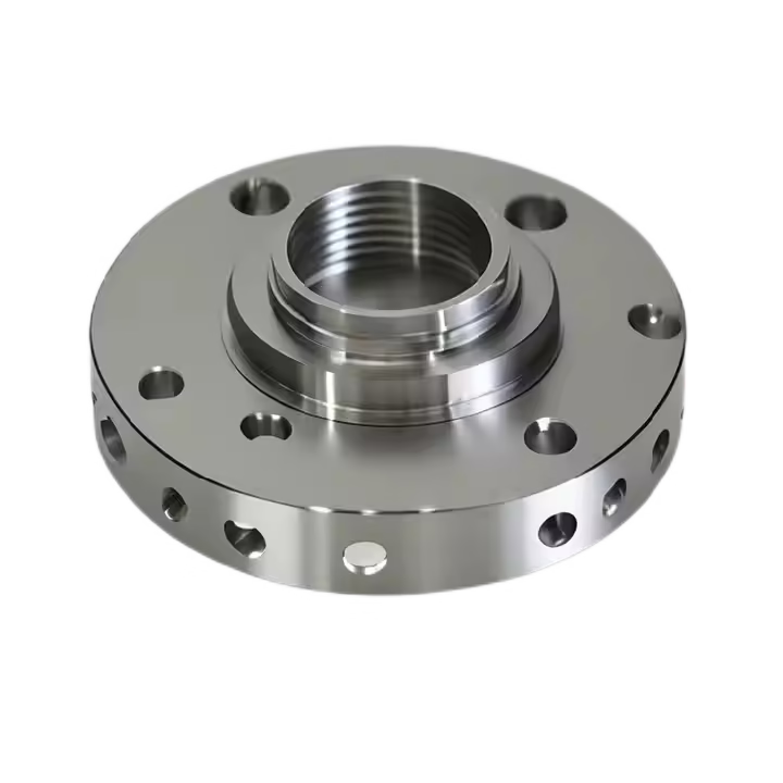
From CAD model to the program that runs a CNC machine
A machinist never types coordinates by hand for a complex part. A designer exports a solid model, a CAM programmer selects tools and cutting strategies, and the software writes the toolpath. That toolpath still is not machine-ready. It is a list of movements in the CAM system's own reference frame, with no idea which spindle, which fixture, or which controller will execute it.
The program that runs a CNC machine is the output of the post-processor: a text file of G-code and M-code written for one specific machine and one specific controller. G-code defines motion and feed. M-code handles machine functions such as spindle start, coolant, tool change, and program stop. The controller reads the file top to bottom and moves the axes.
The distinction matters because a CAM file and a machine program are not interchangeable. Send the wrong post output to a machine and the first rapid move can drive a tool into a vise. The post is where machine limits, work offsets, and safe retract heights get baked in.
One more layer sits on top: the setup sheet. It tells the operator which fixture, which zero point, and which tool numbers the program assumes. Without it, a correct program still runs wrong.
- 1CADGeometry only. No tools, no feeds, no machine.
- 2CAMToolpaths in a neutral frame. Still machine-independent.
- 3Post-processorConverts toolpaths into controller-specific G-code.
- 4Setup sheetTies the program to a real fixture and zero point.
What the controller actually reads
A block of G-code is one line. G00 is rapid positioning, G01 is linear feed, G02 and G03 are circular interpolation. F sets feed in mm/min or in/min. S sets spindle speed. A typical finishing pass on 6061-T6 aluminium might run 8,000 rpm at 1,200 mm/min with a 6 mm carbide end mill, while the same cutter in 17-4PH stainless drops to around 400 mm/min to keep tool load sane.
M-code covers everything that is not motion. M03 starts the spindle clockwise, M08 floods coolant, M06 calls a tool change, M30 ends the program and rewinds. On a mill-turn center these codes also switch between milling and turning modes, which is why the same part can need two programs on one machine.
Controllers are not all equal. Fanuc uses a fairly terse dialect. Siemens 840D supports more advanced cycles and shop-floor variables. Heidenhain on a five-axis machine is written in conversational format that looks nothing like plain G-code, though the CAM post handles that difference automatically.
This is also where subprograms and loops appear. A bolt circle with 24 identical holes does not need 24 hand-written blocks. A subprogram with a rotation offset repeats the cycle, and the file stays short enough for a human to check.
Why 5-axis programs are a different problem
On a three-axis machine, the tool axis is fixed. The post only has to move X, Y, and Z. On a simultaneous five-axis center, two rotary axes move while the linear axes cut, so the controller must solve kinematics in real time to keep the tool tip on the intended path. Our 16 simultaneous 5-axis machining centers also use a Ø400 mm rotary table, and the post has to know that table's pivot distance and the exact spindle gauge length, or the tool will gouge on a contoured surface.
Two numbers dominate the outcome: tool center point management and the inverse-time feed. Tool center point keeps the programmed point at the tool tip when the rotary axes tilt, so the operator can adjust work offset without reprogramming. Inverse-time feed keeps chip load constant when the tool moves along a curved path in five axes, where linear feed would otherwise spike on the inside of a corner.
Not every part needs this. A flat plate with holes is a three-axis job and adding rotary motion only adds risk. Simultaneous five-axis earns its cost on organic curves, deep pockets with undercut walls, and features that would otherwise need three or four separate fixtures.
- 1Good fitImpellers, medical bone plates, thin-wall housings, angled ports.
- 2Poor fitSimple prismatic parts, high-volume simple turning, flat plates.
- 3Watch forShort tool gauge length, rotary table clearance, fixture collisions.
Simulation, post checks, and the first cut
Nobody runs a new program straight onto a finished workpiece. The first pass is a dry run or a machine simulation. CAM software renders the stock removal and flags a collision between holder, fixture, and part. That check catches most errors, but it trusts the same post that wrote the file, so it cannot catch a wrong post setting.
The second check is the post itself. Verify the machine's travel limits, the safe Z retract, and the tool library. A program written for a 750 × 1,150 × 550 mm machine will not run on a compact 500 × 310 × 200 mm machine even if the part is small, because the rapids and the tool change position assume different geometry.
The third check is on the machine. Run the program in single block with rapid override down and the feed override at 10 percent. Watch the distance-to-go display on the first approach. If the number does not match the setup sheet, stop.
Our own flow adds a fourth step: raw material check before the run, in-process monitoring during it, and a final inspection before shipment, with reports on request. A program can be perfect and still produce a bad part if the stock or the fixture is wrong.
Where the program stops and the shop takes over
A program cannot compensate for a machine out of square, a worn spindle, or a fixture that flexes under load. Those show up as taper, chatter, or a size drift across a batch, and no amount of code editing fixes them. The operator reads the symptom and changes the setup or the tool, not the file.
Thermal drift is the common one. A machine that just started will hold a different size than the same machine after four hours of cutting. On a ±0.005 mm tolerance, that difference is enough to matter. Shops that hold tight tolerances warm up the spindle and re-check the first part after the run settles.
Tool wear is the other. A carbide end mill that cuts 6061 cleanly will start pushing material in 316L after a few hundred millimeters of cut. Adaptive toolpaths and constant chip load help, but the operator still decides when to change the insert.
This is why we treat the program as one input among several. Material, tooling, fixture, and inspection all carry equal weight. A well-posted file on a poorly prepared machine loses to a modest file on a controlled process every time.
Program type by machine and part
Match the programming approach to the geometry and the machine, not to habit.
| Machine setup | Typical program | Where it fits |
|---|---|---|
| 3-axis mill | G-code, fixed tool axis | Flat plates, pockets, 2.5D profiles |
| 4-axis mill | G-code plus one rotary index | Shafts, flats around a cylinder |
| Simultaneous 5-axis | Posted with tool center point on | Organic curves, undercut walls, angled ports |
| Mill-turn center | Milling and turning in one file | Parts needing both operations in one setup |
| Conversational control | Shop-floor cycles, not plain G-code | Simple parts, fast turnaround, quick edits |
When to trust the program and when to change the process
If the geometry is prismatic and the tolerance is looser than ±0.05 mm, a standard 3-axis program is enough. If the part has contoured surfaces, thin walls, or features reachable from several directions, pay for a proper 5-axis post and a simulation pass. The program is never the whole answer; the setup around it decides the result.
Questions engineers ask about CNC programs
Is G-code the same as the CAM file?
No. The CAM file holds toolpaths in the software's own frame and can be re-posted for a different machine. G-code is the posted output for one controller and one machine.
You can edit G-code by hand, and machinists do for small changes. Editing the CAM file and re-posting is safer for anything beyond a feed or offset tweak.
Can one program run on two different machines?
Only if both machines share the same controller family and the same travel and tool change positions. Even then, verify safe Z and work offsets.
In practice we keep a separate post for each machine model so the rapids and retracts match the real envelope.
Why does the same program cut differently after a few hours?
Thermal growth in the spindle and ball screws changes the effective position. A machine that just started cuts a different size than one that has run for hours.
Warm up the spindle, then re-check the first part once the machine settles. On tight tolerances this step is not optional.
Does 5-axis always need a special post?
Yes. Simultaneous 5-axis needs a post that handles the machine's kinematics, tool center point, and rotary pivot distances. A generic 3-axis post will produce a file that looks valid and cuts wrong.
The post also has to match the rotary table and spindle gauge length, or contoured surfaces will gouge.
What do you need to quote a machined part?
A 3D model or 2D drawing with tolerances, material, surface finish, and quantity. We return a quotation and a free DFM analysis within 12 hours.
Uploads stay secure and confidential, and an NDA is available on request.
Send the model. We handle the program.
Upload a step file or drawing and our engineers will review the geometry, pick the right machine, and quote it. No minimum order quantity, from one prototype to 10,000+ parts.
12-hour quote100% inspectionISO 9001 · IATF 16949
More from the shop floor
We publish setup notes, tooling trials and inspection data from the factory floor.











