
What Is the Working Principle of a CNC Machine?
A CNC machine reads a program, converts each command into axis motion, and cuts metal or plastic along a defined path. This page explains the loop behind that motion, the parameters that decide accuracy, and the part features where the process stops working.
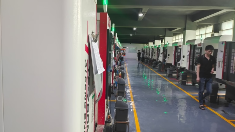
The control loop behind every cut
A CNC machine has no feel for the part. It only knows position. A controller reads a program line, works out where the tool should be at a given moment, and sends that target to a servo drive. The drive turns a ballscrew, the screw moves the table or the spindle, and an encoder reports the actual position back. The difference between target and actual is the following error, and the drive corrects it thousands of times per second.
That loop is the whole working principle of a CNC machine. Everything else — the spindle, the coolant, the tool changer, the way covers — exists to keep the loop accurate and repeatable. If the loop is stable to a few micrometres, the part comes out to print. If the loop chatters or lags, no amount of programming skill will save the dimensions.
Position is not the only variable in the loop. The controller also manages feed rate, spindle speed, and acceleration limits. On a corner, the machine has to slow down or the tool overshoots. Look-ahead blocks read several lines ahead and blend the deceleration, which is why a modern control can hold ±0.005 mm through a curved profile that would have been impossible on an older machine.
The feedback signal itself has a resolution. A 0.1 μm encoder does not mean the machine holds 0.1 μm; it means the drive can see that far. Backlash in the screw, thermal growth in the casting, and tool deflection all sit between the encoder and the cutting edge. Engineers who understand this stop treating the spec sheet as the part tolerance.
How G-code becomes a tool path
CAM software writes the tool path, but the machine does not cut the CAM model. It cuts the programmed path, corrected by the offsets stored in the control. Cutter compensation lets the operator adjust for a tool that measures 9.98 mm instead of 10.00 mm without reposting the program. Wear offsets do the same job after the tool has run a few hundred parts.
Work offsets define where the part sits in the machine envelope. G54 to G59 are the common set. A five-axis machine adds rotary offsets and a pivot distance that must be measured, not guessed. Get the pivot distance wrong by 0.1 mm and every feature on a tilted face shifts in a way that is hard to trace back.
The program also sets the feed rate and spindle speed. These are not fixed numbers. A 12 mm carbide end mill in 6061 aluminium runs very differently from the same cutter in 17-4PH stainless. CAM defaults are a starting point; the shop proves the numbers on the first part.
Modal commands stay active until cancelled. That is efficient, and it is also how a missing G80 leaves a canned cycle running on the next hole. Most scrap on a proven program comes from a modal state that was not reset, not from a wrong coordinate.
Accuracy, repeatability, and thermal drift
Accuracy is how close the machine gets to the commanded position. Repeatability is how close it returns to the same position on the next cycle. For production, repeatability matters more. A machine that is consistently 0.01 mm off can be offset out. A machine that wanders 0.01 mm in both directions cannot.
Heat is the largest slow error in a machine tool. The spindle grows as it warms, ballscrews lengthen, and a 4,000 mm travel machine can move more than a short-travel one. Shops that hold tight tolerances warm up the spindle before the first cut and keep the coolant temperature steady. A cold machine and a warm machine are two different machines.
Tool deflection is the fast error. A long, slender end mill pushed hard will bend and cut undersize, then spring back and leave a witness mark. Reducing radial depth of cut and increasing spindle speed usually beats slowing the feed, because the cutting force drops with the chip load.
Material behaviour closes the loop. Aluminium moves with heat and cuts freely. Titanium work-hardens if the tool rubs. Plastics melt if the chip cannot clear. The same program that holds ±0.005 mm in 6061 may need a different strategy in TC4 or PEEK, and the working principle of the machine has not changed at all.
When CNC is the wrong process
CNC wins when the geometry can be reached by a rotating tool and the batch justifies programming. It loses when the feature is a deep, square internal corner. A cutter has a radius, so a 3 mm deep pocket with a sharp internal corner needs either a smaller tool with a long reach, or a different process. EDM or a cast feature may be cheaper.
Thin walls are another boundary. A 0.5 mm wall in aluminium will deflect under clamping and cutting force. Sometimes the answer is to leave more material, machine in two setups, and remove the support at the end. Sometimes the answer is sheet metal. The decision depends on how many parts and how tight the flatness callout is.
Hardened material changes the economics. Above roughly 45 HRC, carbide struggles and the setup has to be very rigid. Pre-hardening and then grinding, or hard milling with the right tool and a light stepover, are the two common routes. Both are slower than cutting annealed stock.
Finally, cost per part has a floor set by setup, not by cycle time. One prototype and 10,000 parts use the same working principle, but the second one can amortise a fixture. If your annual volume is under 50 pieces and the geometry is simple, a milling setup with soft jaws is usually the honest answer.
Process choice by part feature
Use this to check whether CNC fits the feature before you request a quote.
| Feature | CNC milling / turning | Better alternative |
|---|---|---|
| Sharp internal corner, deep pocket | Needs small tool, long reach | EDM or cast feature |
| Wall under 0.5 mm | Deflects under clamping | Sheet metal |
| Hardened steel above 45 HRC | Light stepover, slow | Grind after hardening |
| Large flat plate, 4,000 mm | Fits long-travel mill | Rolled plate plus machining |
| Smooth free-form surface | 5-axis with ball nose | Casting plus finish pass |
| One-off simple bracket | Soft jaws, one setup | Sheet metal or 3D print |
| High-volume small pin | Mill-turn or Swiss-type | Cold heading |
| Internal thread, blind hole | Tap or thread mill | Thread forming in sheet |
The short answer
If the feature can be reached by a rotating tool and the tolerance is tighter than ±0.05 mm, CNC is the right process. If the corner is sharp, the wall is thin, or the material is already hard, pick a different route before you spend money on a program.
Common questions
Does a CNC machine cut the CAD model exactly?
No. The machine cuts the programmed tool path, corrected by cutter compensation and work offsets. The CAM model is a starting point.
Surface finish, tool deflection, and thermal growth all sit between the model and the finished part.
What tolerance can a CNC machine hold in production?
On a rigid setup with the right tool, ±0.005 mm is achievable on critical features. Ordinary features are usually held at ±0.05 mm to keep cost down.
Tolerance drives cost faster than any other callout. Relax it where the function allows.
Why does the first part differ from the tenth part?
The machine is colder on the first part. Spindle and ballscrew growth move the tool over the first hour of cutting.
Warm up the spindle, check the first article, and apply wear offsets before running the batch.
Can CNC machines cut hardened steel?
Yes, with carbide or ceramic tooling and a light radial stepover. Above roughly 45 HRC the setup must be very rigid.
Many shops harden after machining and grind the critical faces instead.
What decides the surface finish?
Spindle speed, feed per tooth, tool geometry, and rigidity. A sharp tool at the right chip load gives Ra 0.8–1.6 μm without extra work.
A polished finish at Ra 0.2–0.8 μm needs a separate finishing pass and sometimes a finer tool.
Does five-axis change the working principle?
No. It adds two rotary axes to the same position loop. The tool can reach more of the part in one setup.
The trade-off is that pivot distance and rotary offsets must be measured accurately, or the extra reach becomes extra error.
Send us your drawing and we will check the process
Upload a STEP file and our engineers will return a quote plus a DFM note within 12 hours.
12-hour quote±0.005 mm toleranceNo minimum order quantity
More from the shop floor
We publish setup notes, tooling trials and inspection data from the factory floor.











