
What Means CNC Machine?
CNC stands for Computer Numerical Control: a machine tool driven by a program instead of handwheels. This page explains the control loop, where G-code comes from, and which parts actually belong on a CNC. Written for design engineers and buyers who need to judge a process, not memorize a definition.
Key takeaways
What means CNC machine in plain shop language
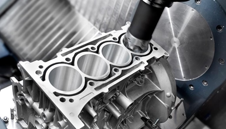
CNC stands for Computer Numerical Control. The phrase describes a control method, not a class of machine. A mill, a lathe, a router, a grinder, a wire EDM and a punch press can all be CNC machines, because all of them can be driven by the same kind of controller reading the same kind of program.
Before CNC, an operator read a drawing and turned handwheels. Position lived in the operator's eyes and hands. A CNC machine moves that information into numbers: the controller tells each axis exactly how far to travel, at what speed, and in what order. The operator's job shifts from turning wheels to loading stock, setting work offsets, and checking the first part.
So when someone asks what means CNC machine, the useful answer is this: a machine tool whose motion is commanded numerically by a computer, repeatably, from a stored program. Everything else, the spindle, the table, the tool changer, is hardware that serves that idea.
That definition matters commercially. Because the program is stored, the same part can be made next month in the same way. Because the motion is numeric, tolerances can be held to ±0.005 mm on a well-set-up machine. And because the program is separate from the hardware, changing the part means changing code, not rebuilding the machine.
- 1ComputerThe controller that reads the program and closes the position loop.
- 2NumericalPositions and speeds expressed as numbers, not feel.
- 3ControlContinuous correction of each axis until the commanded position is reached.
How a CAD model becomes G-code
The chain has four links. A CAD model defines the geometry. CAM software lets a programmer choose tools, stock, workholding and cutting strategy. The CAM output is a toolpath, a set of curves offset from the part surface by the tool radius. A post-processor converts that toolpath into G-code for a specific machine and controller.
G-code is not exotic. A line such as G01 X50.0 Y20.0 F800 means: move in a straight line to X 50.0 mm, Y 20.0 mm, at a feed rate of 800 mm/min. G00 is a rapid move, G02 and G03 are clockwise and counterclockwise arcs, M03 starts the spindle, M06 changes the tool. A typical 3-axis job may run 20,000 to 200,000 lines.
The CAM programmer's real work is not writing code. It is choosing a feasible sequence: which faces to grip, which tool reaches a pocket corner without chattering, where to leave 0.3 mm of stock for a finishing pass. A program that runs without crashing can still produce a part that fails inspection.
One practical note for engineers reviewing a quote. If a feature cannot be reached by a rotating cutter from some tool orientation, it cannot be cut on that machine, no matter how the program is written. Reading a drawing for tool access is often more useful than reading the tolerance block.
- 1CADNominal geometry, no manufacturing intent.
- 2CAMTools, stock, strategy, and toolpath generation.
- 3Post-processorTranslates generic toolpaths into machine-specific G-code.
- 4VerificationSimulation and a first-article check before the run continues.
Why CNC holds tolerance: the feedback loop
A CNC axis is a closed loop. The controller sends a position command to a servo drive. The drive turns the motor, the ball screw moves the slide, and an encoder or glass scale reports the actual position back. The controller compares command and feedback, then corrects. This happens hundreds to thousands of times per second.
Accuracy is therefore not a property of the motor. It comes from the resolution of the feedback device, the stiffness of the machine structure, and the thermal stability of the whole system. A machine with a fine encoder on a flexible frame still cuts a tapered bore. A stiff machine with a worn ball screw repeats the same error on every part.
This is why shops care about warm-up. A spindle that has run for two hours sits in a different thermal state than a cold one, and a 1 °C change across a 500 mm aluminum part can move dimensions by several micrometers. Production runs are often checked against a first article taken after the machine reaches steady state.
It also explains repeatability versus accuracy. Repeatability is how tightly a machine returns to the same point, often a few micrometers. Accuracy is how close that point is to the commanded value. A machine can be highly repeatable and still offset if the work offset or tool length is wrong. That offset is a setup error, and it is corrected without touching the program.
- 1Encoder resolutionSets the smallest position step the loop can see.
- 2Structural stiffnessKeeps cutting forces from pushing the tool off path.
- 3Thermal driftMoves the geometry slowly during long cuts.
- 4Tool wearChanges the effective radius, so dimensions creep over a run.
What the axes on a CNC machine actually do
Three linear axes, X, Y and Z, position the tool in space. A 3-axis mill cuts from one direction, so every feature must be reachable from that direction. This covers a large share of real work: plates, housings, brackets, manifolds, and most mold cavities that are shallow relative to their width.
A fourth axis adds rotation, usually around X. That lets the machine index a part to several faces without re-fixturing, which removes setup error and saves handling time. A fifth axis adds a second rotation, so the tool can be tilted relative to the surface. On a simultaneous 5-axis machine, all five axes move together along the toolpath.
The gain from 5-axis is not just access. Tilting a ball nose cutter off its tip uses the side of the tool, which improves surface finish and lets shorter, stiffer tools reach deep pockets. The cost is programming time and a machine that needs more careful verification, since a wrong tool vector can drive the tool into the fixture.
For turning, the picture is different. A CNC lathe rotates the part against a stationary or driven tool. Two axes cover most turning work, and a mill-turn center adds a milling spindle so a part can be turned and milled in one setup. That single-setup capability often matters more than the axis count on the spec sheet.
- 13-axisOne tool direction; simplest programming and fixturing.
- 24-axisAdds indexing around one axis; cuts setups by 2–4×.
- 35-axisCompound angles, undercuts, and better tool engagement.
- 4Mill-turnTurning plus milling in a single workholding.
Where a CNC machine stops being the right answer
CNC is subtractive. The cutter removes material, so any geometry the cutter cannot reach stays solid. Internal channels that bend, enclosed cavities, and lattice structures are off the table unless the part is split and joined, which adds cost and a joint line.
Volume is the second limit. Setup and programming are fixed costs, so they shrink per part as quantity rises. Past a certain point, a casting or forging die spreads its tooling cost over enough parts to undercut machining. For a simple part with moderate tolerance, that crossover often sits between 5,000 and 10,000 pieces.
Material removal rate is the third. Aluminum cuts fast; titanium and Inconel cut slowly and wear tools. A pocket that takes ten minutes in 6061 can take two hours in Ti-6Al-4V, with more tool changes. The geometry is identical, the cost is not.
None of this makes CNC fragile. It makes it specific. The process rewards parts with accessible features, reasonable aspect ratios, and quantities that do not justify a die. When a design meets those conditions, CNC is usually the fastest route from a CAD file to a functional metal part.
- 1ReachabilityIf a cutter cannot enter, the feature cannot exist.
- 2Aspect ratioDeep, narrow pockets need long tools that deflect.
- 3QuantityHigh volume favors casting, forging or stamping.
- 4Hard alloysTitanium and nickel alloys cut slowly and wear tools.
Which parts belong on a CNC machine
Part geometry and volume decide the process more than the material does.
| Situation | Best fit | Why | Watch out for |
|---|---|---|---|
| 1–100 parts, tight tolerance | CNC milling or turning | No tooling cost, program is reusable | Setup amortized over small quantity |
| Undercuts and compound angles | 5-axis CNC | Tool can be tilted to reach the feature | Higher programming and verification cost |
| Turned features plus milled flats | Mill-turn center | One workholding, fewer datums | Bar size and chuck limits |
| Thin walls under 0.8 mm | CNC with light passes | Controlled chip load reduces deflection | Chatter and spring-back |
| 10,000+ identical simple parts | Die casting or stamping | Tooling cost spread across volume | Upfront tooling lead time |
| Hollow or lattice internal geometry | Additive, then CNC finishing | Machining cannot form internal voids | Support removal on hidden faces |
| Soft or gummy plastics | CNC with sharp tooling | Chip evacuation and cooling matter | Melting and burr formation |
The practical rule
If the part has reachable features, needs ±0.005 mm or better, and the quantity is under a few thousand, machine it on a CNC. If it is a simple shape above 10,000 pieces and tolerance is loose, pay for tooling instead.
Frequently asked questions
Does the C in CNC ever stand for anything else?
In machining, no. C is Computer, N is Numerical, C is Control. The term came from the 1950s when punched tape fed coordinate data to a machine tool, and the name stayed after the tape disappeared.
You will sometimes see CNC written out as computer numerical control machining, which just shifts the noun. The underlying meaning is the same: programmed, numerically commanded motion.
Is a CNC machine the same as a robot?
Not in normal usage. A CNC machine holds a workpiece and moves a cutting tool along a programmed path to create a specific geometry. An industrial robot moves a tool or gripper through space, usually for handling, welding or assembly.
The control technology overlaps. Both use servo drives and closed-loop position control. The difference is the task and the fixturing, not the electronics.
How close can a CNC machine hold a dimension?
On a well-maintained machine with the right setup, ±0.005 mm is achievable, and GreatLight works to that figure. Finer than that, thermal effects, tool wear and fixturing stiffness start to dominate the result.
The tolerance you can hold also depends on the feature. A bored hole in a rigid block is easier than a thin wall on a long part. Send the drawing and the shop can tell you which features are realistic before quoting.
What does CAM do that CAD does not?
CAD defines the shape. CAM decides how a machine makes it: tool selection, step-over, depth of cut, entry strategy, workholding, and the order of operations. A good CAM setup is what keeps a thin part from distorting.
That is also why the same CAD file can be quoted at different prices. Two shops may choose different stock, different fixtures and different toolpaths for the same geometry.
Can any material be machined on a CNC machine?
Most metals and plastics can, with the right tooling and speeds. Aluminum, stainless steel, tool steel, copper alloys, titanium, Inconel, PEEK and ABS are all routine in a job shop.
What changes is the cutting data and the cost. Hardened tool steel above 45 HRC is usually ground or EDM-cut rather than milled. Very soft plastics need sharp tools and generous chip clearance to avoid melting.
Do I need a 5-axis machine for my part?
Usually not. If every feature is reachable from one or two directions, a 3-axis machine with a couple of setups is cheaper and faster. A 5-axis machine earns its cost when the part has compound angles, deep pockets, or surfaces that need a tilted tool for finish.
A quick test: sketch the cutter entering each feature. If a straight tool from a single direction reaches everything, stay with 3-axis.
Send a drawing, get a manufacturability answer
We review your files for tool access, tolerance and material, then quote with a free DFM analysis. Uploads stay confidential and an NDA is available on request.
12-hour quoteFree DFM analysis100% inspectionNo minimum order
More from the shop floor
We publish setup notes, tooling trials and inspection data from the factory floor.











