
What Files Do CNC Machines Use?
CNC machines do not read your CAD model directly. They read G-code, and G-code comes from a chain of file formats that starts with your design intent. This page explains each step for engineers and buyers who need to send a file that will actually cut a part.
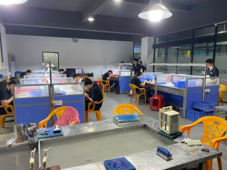
What files do cnc machines use at the control?
A CNC machine never opens a CAD file. The control reads a program of G-code and M-code, line by line, and moves the axes to the coordinates in that program. Everything upstream of the control exists to produce that program correctly. When engineers ask what files do cnc machines use, the honest answer is one format at the machine and several formats before it.
The phrase Sirius file is not a machining format we recognize. It may be a file from a specific CAD system, an internal naming convention at your company, or a mishearing of a file extension. In our shop we treat it the same way we treat any unknown format: ask for the native CAD file, then check whether the geometry is a solid or a surface model.
That check matters more than the extension. A solid model lets us verify wall thickness, fillet radii and tool clearance before quoting. A surface model or a mesh often hides gaps that only show up when the toolpath is generated. Fixing them after the program is written costs time on both sides.
So the practical answer has two parts. The machine uses G-code. Your design reaches us as a CAD or exchange file, and the format you pick decides how much of your design intent survives the trip.
- 1G-codeThe only format the machine control reads
- 2STEP, IGES, ParasolidSolid exchange formats we prefer
- 3STL, OBJMesh formats, usable but limited
- 4DXF, PDF2D profiles and drawing views
Native CAD files and exchange formats
Native files come from the software you designed in: SolidWorks, Fusion 360, Inventor, NX, Creo, CATIA. They carry the full feature tree, sketches, constraints and material assignments. If we run the same software version, a native file is the richest input you can send. The catch is version lock and license cost on our side.
Exchange formats solve that. STEP (AP203 or AP214) and Parasolid store boundary representation data, which means precise surfaces and edges rather than a faceted approximation. IGES is older and weaker on solids, but it still appears in aerospace documentation packs. For most turned and milled parts, STEP is the safe default.
Send a STEP file when the part is a single solid or a small assembly and you want us to see true geometry. Send a native file when the part has complex surfacing or thin walls and you want us to inspect the feature tree. Send IGES only when a customer or a legacy system forces it.
One habit saves a round trip. Export STEP at high precision, not the default medium setting. A loose export tolerance can round off a 0.5 mm chamfer or a small corner radius before the file ever reaches us.
- 1STEPBest all-round solid exchange format
- 2ParasolidStrong on complex solids, common in NX shops
- 3IGESLegacy surfaces, avoid for new work
- 4NativeRichest data, needs matching software version
What CAM adds and why the post-processor matters
CAM software turns your solid into toolpaths. Mastercam, Fusion 360, HyperMill and NX CAM all hold the same kind of data: operation order, stepover, feed and speed, tool library, workholding. The CAM project file is not portable. Send it to a shop running different software and it opens as an empty shell or not at all.
The post-processor is the step most people miss. A toolpath is machine-neutral. The post converts it into G-code for a specific control, and every control speaks a slightly different dialect. A Fanuc mill and a Siemens control handle canned cycles, arc moves and tool length offsets differently.
This is why we write our own programs for production parts. If you send G-code from your own CAM seat, we can run it only if the machine, control and fixture match your setup. For a one-off prototype on your own machine that works. For parts we machine on 16 simultaneous 5-axis centers, we re-post from the solid.
Verification happens before the first cut. We check tool reach against the holder, simulate the toolpath, and confirm that every surface the drawing calls out is reachable in the number of setups we quoted. A missing toolpath is cheaper to find in simulation than in titanium.
- 1CAM projectToolpaths and strategy, tied to one software
- 2Post-processorConverts toolpaths into control-specific G-code
- 3SimulationCatches collisions and gouges before cutting
- 4Setup countDrives cost more than file size does
Mesh files, 2D files and where each one stops
STL and OBJ describe a shape as triangles. There are no true cylinders, no threads, no tolerance callouts. A hole becomes a polygon with visible flats. For 3D printing that is fine because the printer slices layers anyway. For CNC turning at ±0.005 mm it is not, because the control needs arc centers and true diameters.
DXF is a 2D format. One profile, one cut path, no height information. It is the right input for sheet metal fabrication, laser cutting and waterjet work. If you send a DXF for a 3D milled part, we can only see the outline, and we will ask for a solid model before quoting.
PDF drawings sit beside the model, not instead of it. They carry the dimensions, tolerances, surface finish callouts and material notes that a 3D file cannot express. A GD&T frame or a Ra 0.8–1.6 μm finish note has no place in STEP geometry. Send both.
The failure pattern is consistent. A mesh with a rounded corner that should be sharp, a DXF for a part with pockets, a drawing that says Ø12 H7 while the model shows Ø12.0 nominal. Any of these sends the job back for clarification, and a clarification loop costs a day.
- 1STLGood for a visual check, weak for tolerances
- 2DXF2D only, ideal for flat cut parts
- 3PDF drawingCarries GD&T, finish and material notes
- 4BothSend 3D model plus drawing for best results
When a format is the wrong choice
A STEP file is not always enough. If the part has a thread, a knurl or a laser-marked logo, those features may be suppressed in the exported solid. Put them in the drawing notes with a clear callout. Marking text below 1.5 mm character height is not practical to engrave, so flag it early.
Very large assemblies are another edge case. A full machine assembly with thousands of components takes time to open and hides the one part you actually need. Send the individual part or a simplified assembly. If you need fit checks across several parts, tell us which interfaces matter.
For thin-wall parts, add a note about the minimum wall you can accept. A 0.5 mm wall in aluminium 6061 behaves differently from the same wall in PEEK. The file will not tell us your intent, and the toolpath strategy changes depending on the answer.
Finally, do not send a proprietary or unknown format and expect it to open. If the extension is not one we list, export it to STEP or send the native file with a screenshot. We will come back with a DFM note within 12 hours either way.
- 1Threads and knurlingOften missing from exported solids
- 2Large assembliesSend the single part, not the whole machine
- 3Thin wallsState the minimum wall you can accept
- 4Unknown formatExport to STEP or send a native file
Which file format fits which part
Pick the format by geometry type, not by habit.
| Format | What it carries | Use it when | Watch out for |
|---|---|---|---|
| STEP (.step, .stp) | Solid B-rep geometry | Milled or turned 3D parts | Loose export tolerance rounds small radii |
| Parasolid (.x_t) | Solid B-rep, tight tolerances | Complex solids, NX-based workflows | Some viewers cannot open it |
| IGES (.igs) | Surfaces and wireframe | Legacy aerospace data packs | Gaps between surfaces, no solid body |
| STL (.stl) | Triangulated mesh | 3D printing, rough checks only | Flat facets, no true arcs or threads |
| DXF (.dxf) | 2D profiles and cut paths | Sheet metal, laser, waterjet | No Z data, no 3D features |
| PDF drawing | Dimensions, tolerances, notes | Always send with the 3D model | Never machine from a PDF alone |
| NC / G-code (.nc, .tap) | Toolpaths for one control | Only if you own the machine setup | Not portable between controls |
Which file should you send
Send a STEP AP214 solid plus a PDF drawing with tolerances and finish callouts. That pair covers 3D geometry and the notes a model cannot hold. If your part is flat and cut from sheet, send DXF instead. G-code only travels well when the machine and control match ours, so we re-post from your solid.
Frequently asked questions
Is a Sirius file a real CNC format?
We have not seen Sirius used as a standard machining file format. It is most likely a native file from one CAD system, an internal naming convention, or a typo for another extension.
Send us the file or a screenshot and we will tell you what it contains. If it holds solid geometry, we can usually convert it to STEP and quote from that.
Can you machine directly from an STL file?
For simple prismatic parts, sometimes. The mesh is faceted, so curved surfaces come out with small flats and tight tolerances are hard to hold.
For anything with threads, bores or a tolerance below ±0.05 mm, we ask for a STEP or native solid. STL is best kept for a quick visual check or for 3D printing.
Do you need the drawing if you have the 3D model?
Yes. The model shows shape. The drawing shows intent: tolerance bands, surface finish, material temper, and which faces are datums.
If no drawing exists, we can work from the model alone, but we will send a DFM note listing the tolerances and finishes we plan to apply so you can confirm them.
What if my CAD software is not on your list?
Export to STEP AP214 or Parasolid and send that. Both formats carry solid boundary data and open in most CAM systems without loss.
Include a PDF drawing and a screenshot of the model tree if the part has complex surfacing. That combination is enough to quote and to program.
How large a file can you accept?
File size is rarely the limit. Our maximum processing size is 4,000 mm, and we run parts on 127 high-precision CNC machines including 16 simultaneous 5-axis centers.
The real limit is geometry clarity. A 200 MB assembly with hidden internal parts helps less than a clean single solid with a drawing.
Can I send G-code from my own CAM system?
Only if the machine, control and fixture match your setup. G-code is not portable between controls because canned cycles, arc handling and offsets differ.
For production we re-post from your solid model, which also lets us adjust the setup for our own workholding and inspection plan.
Send the right file and get a quote in 12 hours
Upload your STEP file and drawing. We return a quotation and a free DFM analysis within 12 hours, and production can start within 24 hours.
12-hour quote100% inspectionNDA on request
More from the shop floor
We publish setup notes, tooling trials and inspection data from the factory floor.











