
What Was the First CNC Machine? The 1952 NC Breakthrough Explained
The first numerically controlled machine did not appear in one moment. It grew out of a 1949–1952 US Air Force project at MIT, where a Cincinnati Hydrotel milling machine was driven by punched tape instead of handwheels. This page explains the machine, the control chain, and why the difference between NC and CNC still shows up in the tolerances and part geometry shops quote today.
Key takeaways
The 1952 Hydrotel and the First NC Control Chain
The machine was a Cincinnati Hydrotel vertical mill. MIT's Servomechanisms Laboratory replaced the handwheels with servo drives and a controller that read a punched tape. The tape carried coordinate and feed commands that had been calculated earlier on a large computer, then converted into the binary pattern the tape reader could step through.
The computer was not wired to the mill in real time. Operators prepared the data offline, punched it, and loaded the tape. That detail matters, because it separates the 1952 demonstration from what we now call computer numerical control. The machine was numerically controlled, but it was not yet computer controlled in the closed-loop sense engineers mean today.
Four links made the chain work: a command source, servo drives on each axis, position feedback, and a way to measure the finished part against the intent. Every modern machine still contains those four links. The materials changed, the electronics changed, and the software changed. The skeleton did not.
The Air Force cared about the same thing a buyer cares about now. Complex contoured surfaces, cut repeatably, by a shop that is not the only shop that can cut them. Aircraft skins, spar caps, and engine hardware pushed the requirement. Job shops followed once the cost of control hardware dropped.
- 1CommandCoordinates and feeds, first on tape, today on a program file.
- 2DriveServo motors on each axis replace handwheels and lead screws.
- 3FeedbackAxis position reported back so the controller can correct error.
- 4InspectionThe part is measured against the drawing, not against the program.
How the Control Chain Evolved from Tape to Stored Program
NC machines read a fixed medium. To change a cut, you cut a new tape or spliced an old one. The program lived outside the machine. Setup time was long, and any error found mid-run meant stopping, editing paper, and re-running the whole cycle from the top.
CNC moved the program inside. A dedicated microcomputer stores the code, lets a machinist edit offsets and feed overrides at the panel, and repeats the cycle without re-reading a physical master. That single change turned a tape-driven mill into a flexible tool. Simulation became possible, tool compensation became normal, and CAD/CAM files could post directly to the control.
The practical gap shows up in three places. First, feature count: a CNC can hold hundreds of small moves and tool changes in one program. Second, correction speed: an offset change takes seconds, not a new tape. Third, traceability: a modern controller logs spindle load, tool life, and alarm history.
Neither system fixes a bad setup. A tape-driven mill with a rigid fixture and a sharp cutter can beat a poorly fixtured CNC on surface finish. Control sophistication does not replace clamping, tool geometry, or thermal stability. It only makes the good setup repeatable.
- 1Program storageNC keeps it on tape, CNC keeps it in onboard memory.
- 2Edit at the panelCNC allows offset and feed changes mid-run. NC does not.
- 3SimulationCNC can dry-run the path in software before cutting metal.
- 4Data outCNC machines report tool life and alarms. Tape machines do not.
Why the 1952 Machine Still Sets Today's Tolerance Budget
The 1952 project proved a claim that still governs quoting: geometry can be generated from numbers, so accuracy depends on the machine, the tool, and the measurement loop, not on the operator's hand. Every tolerance discussion in a modern shop is a variation of that idea.
In practice, tolerance is consumed by four things. Machine positioning error, tool deflection, thermal drift, and the fixture. On a rigid part with a stable setup, a good 3-axis machine can hold ±0.005 mm on a critical bore. On a thin-wall aluminum housing, the same machine may struggle to hold ±0.05 mm because the part moves as it is cut.
This is why the number on a drawing has to match the feature. A tight true position on a hole pattern in one setup is routine. The same tolerance across three setups, with a re-clamp in between, is a different problem. The historical lesson is not that old machines were crude. It is that control accuracy and part accuracy are two different numbers.
When a buyer asks for ±0.005 mm, the honest answer depends on geometry. We look at wall thickness, feature depth, datum scheme, and material before agreeing to a tolerance band. A 5-axis setup that machines five faces in one clamp removes the re-clamp error entirely, and that is usually the real lever.
- 1Machine errorPositioning and repeatability of the axis drives.
- 2Tool deflectionLong reach or small diameter tools bend under load.
- 3Thermal driftSpindle and ball screw growth over a long run.
- 4Fixture and clampRe-clamping between setups adds a new error stack.
From One Tape-Driven Mill to 127 CNC Machines
The jump from one demonstration machine to a production floor took decades. Servo costs fell, controllers became commodity electronics, and CAD/CAM replaced manual coordinate calculation. By the 1990s a job shop could buy a machining center with tool changers and a full enclosure for less than the cost of the 1952 controller alone.
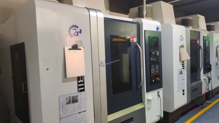
A modern shop runs mixed work on the same floor. In our Dongguan and Singapore plants we run 127 high-precision CNC machines, including 16 simultaneous 5-axis machining centers, 12 four-axis mills, 27 three-axis machines, and 16 mill-turn centers. Maximum processing size reaches 4,000 mm, with travels of 4,000 × 400 × 150 mm on the large frame and 750 × 1,150 × 550 mm on the medium frame.
The work split follows the same logic as the 1952 project. Simple prismatic parts with loose tolerances go on 3-axis machines. Parts with compound angles, deep pockets, or five faces of features go on 5-axis. Turned parts with milled flats go on mill-turn centers. Putting the wrong part on the wrong machine is the most common cost error in quoting.
Materials follow the geometry. Aluminum 6061-T6 and 7075 are the default for prototypes and housings. Stainless 303 and 17-4PH cover corrosive and high-strength work. Titanium Ti-6Al-4V and Inconel show up in aerospace and energy parts, where tool wear drives cycle time more than machine speed does.
- 13-axisFlat plates, brackets, simple pockets, one face at a time.
- 24-axisCylindrical parts with flats, slots, and cross holes.
- 35-axisCompound angles, impellers, five-sided features, one clamp.
- 4Mill-turnShafts and fittings that need turning and milling in one cycle.
NC, Early CNC, and Modern CNC Compared
The control chain changed more than the metal cutting did.
| Attribute | NC (1952–1970s) | Early CNC (1970s–1990s) | Modern CNC |
|---|---|---|---|
| Program source | Punched tape, fixed master | Onboard memory, panel edit | CAD/CAM post, network file |
| Change a cut | Re-punch the tape | Edit at the control | Repost from CAM |
| Axes typical | 3 axes, one at a time | 3 to 4 axes | Up to 5 simultaneous |
| Position feedback | Resolver, coarse | Encoder, closed loop | Linear scales, thermal comp |
| Setup count | Many, per face | Two to three | One clamp is common |
| Tolerance typical | ±0.05 mm or looser | ±0.02 mm | ±0.005 mm on rigid parts |
| Surface finish | Ra 3.2 μm and up | Ra 1.6–3.2 μm | Ra 0.2–1.6 μm |
| Traceability | Paper traveler | Paper plus basic log | Digital log, tool life data |
Control History Tells You Which Machine to Pick
If the part is prismatic with generous tolerances, a 3-axis machine is the cheaper and faster choice. If the tolerance is tight or the features sit on several faces, use 5-axis and machine it in one clamp, because reducing setups removes more error than any control upgrade can. The 1952 lesson still holds: the machine generates the geometry, but the setup decides whether the geometry is correct.
Frequently Asked Questions
Was the 1952 machine a CNC or an NC machine?
It was an NC machine. The control data was prepared offline on a large computer, punched into tape, and read by a tape reader on the mill. The computer was not connected to the machine during the cut.
CNC, in the sense of an onboard computer that stores and edits the program, arrived later. The term entered common use in the 1970s as microcomputers became cheap enough to mount on the machine.
What was the first part cut on it?
The demonstration parts were simple contoured surfaces chosen to prove that a tape-driven servo system could follow a calculated path. The point was the path, not the part.
Early NC work was aimed at aircraft components with complex curves, because those were the parts that manual layout and hand feeding could not repeat reliably.
Why did the aerospace industry push NC development?
Aircraft structures use large, thin, curved parts with many closely spaced features. Hand layout and manual milling produced variation that was expensive to correct and hard to inspect.
A tape-driven machine repeats the same path on every part. That made inspection simpler and let one shop produce parts another shop could also produce, which mattered for a supply chain with many subcontractors.
Does an older control limit the tolerance I can get?
Usually the control is not the bottleneck. Tool deflection, fixture rigidity, thermal drift, and part stiffness set the practical limit on most work.
A modern control helps by allowing fine offset changes and by logging data. It does not make a flexible part rigid.
How do I know if my part needs 5-axis machining?
Look at where the tolerances sit. If tight features are on more than two faces, or if the part has compound angles, 5-axis machining in one clamp usually beats three setups on a 3-axis machine.
If the tight features are all on one face and the part is rigid, a 3-axis machine is faster and cheaper. Send the drawing and we will say which route fits.
What tolerance and finish can you hold today?
We hold ±0.005 mm (±0.0002 in) on suitable features, with surface finish from Ra 0.2–0.8 μm on fine work to Ra 1.6–3.2 μm as-machined.
Every part is inspected before shipment, with raw material check, in-process monitoring, and final inspection. Reports are available on request.
Send the Drawing, Get a Machining Route
Upload a STEP file and we will tell you which machine fits, what tolerance the geometry can actually hold, and where the cost sits. Quotation and free DFM analysis within 12 hours.
12-hour quote100% inspectionNo minimum orderNDA on request
More from GreatLight
We publish setup notes, tooling trials and inspection data from the factory floor.











