
Who Invented 3D Printing? The Engineering Answer
Three people filed the first working patents: Hideo Kodama in 1981, Chuck Hull in 1984, Carl Deckard in 1989. This page explains what each process actually does, where it stops, and when a printed part needs CNC machining before it ships.
In this article
- 1
- 2
- 3
- 4
- 5
- 6
- 7
- 8
- 9
Key takeaways
Who Invented 3D Printing? Three Filings, Not One
Ask who invented 3D printing and most people expect one name and one eureka moment. The patent record is messier. At least three separate groups built working layer-by-layer machines within eight years of each other, and each one opened a branch of additive manufacturing that is still in use today.
Hideo Kodama, working at the Nagoya Municipal Industrial Research Institute, filed a patent application in 1981 for a system that cured photopolymer resin with ultraviolet light in stacked patterns. His hardware already had the three elements every SLA printer still has: a resin vat, a moving platform, and a light source that draws one thin layer at a time.
Kodama did not commercialize it. The filing was incomplete, funding was thin, and the industrial interest was not there. He published and moved on. If you want the literal first working process, his name belongs at the top of the list. If you want the person who turned it into an industry, keep reading.
The distinction matters for engineers. A patent is a description of a mechanism. A production process is a mechanism plus a material supply chain, a calibration routine, and a way to hold tolerance across thousands of parts. Those are different achievements.
Chuck Hull and the Stereolithography Patent
In 1984 Chuck Hull was working for a company that made ultraviolet lamps for coating tabletops. He was tired of waiting weeks for prototype parts, so he designed a machine that built objects from photopolymer resin, one cured layer at a time.
Hull filed in 1984 and the patent issued in 1986. He coined the term stereolithography, and the file format he defined for describing a solid as stacked triangles is still the default in every slicer today. That format, not the machine, is why his name sticks.
He also did the commercial work Kodama skipped. He co-founded 3D Systems, shipped the first SLA machine, and built a resin supply chain around it. A process only becomes an industry when somebody sells the consumables.
The engineering consequence of SLA is straightforward. Because the part is cured from a liquid, the as-built surface is smooth but dimensionally soft. Resin shrinks as it cures, so a 100 mm feature can drift 0.1 to 0.3 mm depending on geometry and post-cure. That number is fine for a form study and useless for a bearing bore.
Carl Deckard and the Metal Powder Branch
The third thread runs through the University of Texas at Austin. Carl Deckard and his advisor Joe Beaman developed selective laser sintering, a process that fuses powder with a laser instead of curing liquid resin. Their patent issued in 1989.
SLS started with plastics and moved to metals. That line of work became direct metal laser sintering and selective laser melting, the processes behind most printed titanium and Inconel parts today. Without Deckard's branch, additive manufacturing would still be a prototyping tool for visual models.
Powder-bed metal printing solves the material problem and creates a new one. The part comes out of the build plate attached to support structures, with a grainy surface and internal stress from repeated heating and cooling. It must be stress-relieved, cut off, and usually machined on every critical face.
That is the boundary that matters on a shop floor. Printing gets you a near-net shape in a hard alloy. It does not get you a sealing face, a threaded port, or a bore that accepts a press-fit bearing.
Why Printed Parts Still Need Machining
Printing builds up, machining cuts away. That sounds like a philosophical split but it shows up as a practical one on the drawing. Additive gives you geometry that would be impossible or expensive to cut, such as internal channels that follow a curved wall or a lattice that saves 40% of the mass.
Subtractive work gives you control over the last 20 to 50 μm. It is the only reliable way to hit a flatness callout, a bore diameter, or a thread that has to pass a gauge. A printed aluminum housing might be dimensionally correct on the outside and completely unusable at the seal groove.
The gap is not a failure of additive manufacturing. It is the nature of the process. Every layer is a thermal event, and thermal events leave residual stress, porosity, and a rough skin. Machining removes all three at once.
That is why the two processes are usually sequenced rather than compared. Print the near-net shape to save material and cycle time. Machine the critical features to hit the tolerance the assembly actually needs.
Hybrid Manufacturing in Practice
A realistic hybrid workflow starts with a decision about which features carry function. A bracket might have four bolt holes, one precision bore, and a large organic web. The web is a good candidate for printing. The bore is not.
We leave 0.3 to 0.5 mm of stock on every face that will be machined. That allowance covers distortion, support removal marks, and the difference between the printed datum and the machined datum. Then we clamp on a printed surface, establish a datum from the machined face, and cut the rest.
The order matters. Machining the datum first gives every later operation a reliable reference. Cutting the cosmetic surfaces first usually means re-clamping on a rough surface and chasing your own error.
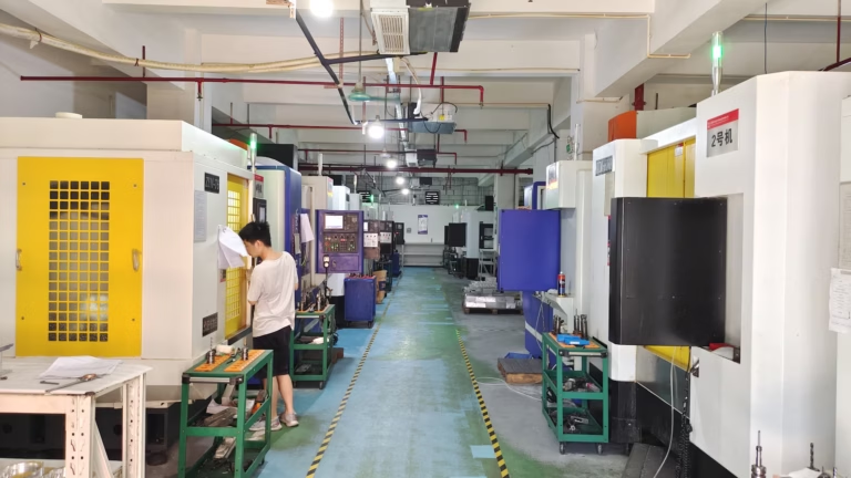
On our 5-axis centers, features that would need three separate setups on a printed part can be cut in one. We hold ±0.005 mm and finish to Ra 0.2–0.8 μm when the drawing calls for it, on materials that range from 6061-T6 to Ti-6Al-4V.
Do Printed Material Properties Match the Data Sheet?
Short answer: usually not, and the gap is predictable. A printed part is anisotropic. It is strong in the plane of the layers and weaker across them. A data sheet produced from a cast or wrought coupon will not describe that behavior.
Porosity is the second issue. Powder-bed parts can retain gas pockets that only show up after machining opens a surface. If the part has to hold pressure or pass a dye penetrant check, the printed skin is not a reliable barrier.
Heat treatment helps but does not erase the difference. Stress relief reduces distortion during machining. Hot isostatic pressing closes internal voids. Neither restores the wrought grain structure of a rolled bar.
For a load-bearing part, the honest answer is often to machine from wrought stock and use printing only where the geometry genuinely cannot be cut. That is a cost decision as much as a metallurgical one.
SLA, SLS and CNC: What Each Process Actually Delivers
Typical values for general engineering work, not a guarantee for a specific part.
| Process | Typical tolerance | Surface as built | Best fit |
|---|---|---|---|
| SLA resin | ±0.1 to ±0.3 mm | Ra 1.6–3.2 μm | Form studies, clear housings, masters |
| SLS polymer | ±0.2 to ±0.4 mm | Ra 6–15 μm | Ducts, brackets, low-load fixtures |
| Metal powder bed | ±0.1 to ±0.5 mm | Ra 8–20 μm | Lattice parts, conformal cooling |
| 5-axis CNC | ±0.005 mm | Ra 0.2–0.8 μm | Mating faces, bores, threads, seals |
When to Print, When to Machine, When to Do Both
| Situation | Route | Reason |
|---|---|---|
| Concept model, no fit | Print only | Speed beats tolerance at this stage |
| Internal channel, no mating face | Print only | CNC cannot reach the geometry |
| Bearing bore under Ø20 mm | Machine only | Roundness and size need cutting |
| Organic bracket with 2 critical bores | Print then machine | Saves material, keeps the fit |
| Sealing face or O-ring groove | Machine after print | Surface and flatness decide the seal |
| Production run above 10,000 | Machine or cast | Per-part cost favors subtractive |
The Verdict
If the part is a visual or fit-check model, print it and ship it. If it has a bore, a thread, a seal, or a tolerance tighter than ±0.05 mm, print the near-net shape and let CNC decide the final size. Choose one route only when the geometry or the volume clearly rules the other out.
Frequently Asked Questions
Who actually invented 3D printing first?
Hideo Kodama filed the first working patent application for a layer-by-layer photopolymer process in 1981 at the Nagoya Municipal Industrial Research Institute.
Chuck Hull filed a separate stereolithography patent in 1984 and commercialized it through 3D Systems. Most histories credit Hull because his process reached the market first.
What is the difference between stereolithography and selective laser sintering?
SLA cures liquid photopolymer resin with ultraviolet light, so the part comes out smooth and needs support removal and post-cure.
SLS fuses powder with a laser, which means no support structures in the same sense and a grainy surface. SLS also extends to metals, which is where printed titanium and Inconel parts come from.
Can a 3D printed part hold ±0.005 mm?
Not as printed. Resin shrinkage, layer height and thermal distortion put practical as-built accuracy in the ±0.1 to ±0.5 mm range depending on the process.
±0.005 mm is achievable on a printed part only after CNC machining of the critical features.
Why machine a part that was already printed?
Machining fixes three things at once: size, flatness and surface finish. It also removes the rough printed skin and any surface porosity that would show up in a sealing application.
We typically leave 0.3 to 0.5 mm of stock on faces that will be cut after printing.
Does printing cost less than CNC machining?
For one complex geometry with internal channels, printing is often cheaper because it avoids multiple setups and long cycle times.
For simple prismatic parts or volumes above 10,000 pieces, CNC machining or die casting usually wins on per-part cost.
What file format do you need to quote a hybrid part?
Send a STEP file for the finished geometry plus a note on which features are critical. We return a DFM analysis and quotation within 12 hours.
If the part will be printed first, mark the machining allowance so we can separate the as-printed and as-machined dimensions.
Send the Drawing, Get a Straight Answer
Upload your STEP file and we will tell you which features to print, which to cut, and what tolerance the process can actually hold.
12-hour quote100% inspectionNo minimum order quantity
More from GreatLight
We publish setup notes, tooling trials and inspection data from the factory floor.











