
Who Invented CNC Machine? The Team, the Contract, and the Control Loop
The answer is not one person. It is a machinist named John Parsons, a MIT servomechanism lab, and a 28-ton milling machine rebuilt in 1952. This page explains what each party actually contributed, how NC became CNC, and how that control chain still sets the limits on what we can cut today.
In this article
- 1
- 2
- 3
- 4
- 5
- 6
- 7
- 8
Key takeaways
The Precursors: Punched Cards Before Servo Motors
Long before anyone asked who invented CNC machine, machine tools already followed stored instructions. Cam-operated screw machines, Jacquard-style punched cards on textile looms, and tracer mills that copied a master template all separated the shape from the operator's hand. The shape lived in a physical medium, not in the machinist's wrist.
The limitation was rigidity. A cam or a template fixes one geometry. Change the airfoil, and you cut a new cam. For a company making many low-volume profiles, that meant weeks of pattern work before the first chip came off.
Tracer milling was the closest ancestor. A stylus followed a master and the cutter copied it. Accuracy depended on the master, and the master wore with use. Nobody could edit a path by typing numbers.
- 1Cam and templateShape is fixed in hardware; one geometry per setup.
- 2Tracer millCopies a master; accuracy drifts as the master wears.
- 3Missing pieceA way to change the path without cutting new hardware.
The Key Innovators: Parsons, MIT, and the 1949 Contract
John T. Parsons ran a company making helicopter rotor blades in the 1940s. Airfoil skins needed smooth, aerodynamically correct contours, and manual layout could not hold that shape at a sane cost. Parsons had an idea that sounds obvious now: compute a series of coordinate points on an IBM accounting machine, then feed those points to a machine tool so the cutter follows them.
In 1949 he secured a U.S. Air Force contract to develop a numerically controlled milling machine. His shop could not build the servo drives and feedback electronics the idea required. That gap is why the credit is split.
The Air Force routed the hardware work to the Servomechanisms Laboratory at the Massachusetts Institute of Technology. There, a team led by J. Francis Reintjes, with Alfred Susskind working on the control mathematics and programming, built the controller that could read coded instructions and drive each axis.
The machine they retrofitted was a 28-ton Cincinnati Milacron Hydro-Tel vertical spindle contour milling machine. The 1952 demonstration is the point most people mean when they ask who invented CNC machine. Parsons framed the problem, MIT built the loop, the Air Force funded both.
From NC to CNC: What Actually Changed
The 1952 machine was NC, not CNC. Numerical control means the axis commands are numbers, but the sequence lives on punched tape, magnetic tape or a plugboard. The controller reads a fixed block of data and moves. There is no stored program in memory you can edit at the console.
Punched tape brought its own failure modes. A mispunched hole, a torn tape, a reader misaligned by a few thousandths of an inch, and the tool went to the wrong place. Operators learned to dry-run a tape with the cutter clear of the stock, and tape splicing became a trade skill.
CNC arrived when a dedicated computer took over the interpreter role. The program sits in memory, the machine can be re-posted for a different part in minutes, and features like cutter compensation, canned cycles and tool-length offsets became software instead of hardware wiring. Direct numerical control then linked several machines to a host, and today the controller is a networked PC on the shop floor.
The engineering meaning is simple. NC fixed the geometry in a fragile medium. CNC moved the geometry into editable memory and put a real-time computer between the program and the servo.
- 1NCNumbers on tape, hard-wired logic, no on-machine editing.
- 2CNCStored program, software offsets, fast changeover.
- 3DNC and afterNetworks and file transfer replace the tape reader.
Why the 1952 Control Loop Still Sets Your Tolerance
Every CNC machine on a shop floor runs the same loop MIT had to solve: read a block, interpolate a path, command a velocity, read position feedback, correct the error. Whether the part is a 4,000 mm airframe rib or a Ø400 mm rotary-table job, the accuracy ceiling comes from how fast and how accurately that loop closes.
Interpolation is where the loop shows up in the part. The controller breaks a G01 move into tiny segments and coordinates two or more axes. If the servo lags on the outside of an arc, the cutter leaves the path and you measure a chord error. That is why feed rate and corner rounding interact, and why a program that holds ±0.005 mm on a straight wall can drift on a tight radius.
Backlash and thermal growth sit on top of the loop. Ballscrew backlash shows as a step when an axis reverses direction. Spindle and ballscrew heat pushes the tool deeper into the cut over a long run. On a 127-machine floor, we control both with reversal checks, warm-up cycles and in-process probing.
Surface finish follows the same logic. A fine Ra 0.2–0.8 μm finish needs a stable loop, a sharp edge and a light finishing pass. If the servo hunts, you get chatter marks no insert geometry can hide.
- 1Servo lagShows as arc chord error on fast contouring moves.
- 2BacklashShows as a step at every axis reversal.
- 3Thermal driftShows as a slow size trend across a long run.
When a CNC Machine Is the Wrong Tool
The history explains the limits. CNC pays off when the geometry repeats and the setup can be amortized. It is a poor fit for one-off parts with no drawing, for organic shapes that a casting or an additive build produces in one piece, and for features a press or a die can stamp in a fraction of the cycle time.
Machining also loses on hollow internal channels. A conformal cooling channel inside a mold insert or a lattice inside a bracket is a casting or 3D printing job. Cutting those features means splitting the part, and every split adds a seam, a fixture and an assembly step.
Soft, abrasive or gummy materials can be a poor fit too. Some plastics smear instead of shearing, and beryllium copper and magnesium alloys need specific tool geometry and coolant practice. That does not make CNC impossible, but it changes the process window.
The practical test is repeat count, tolerance and feature access. If the part needs ±0.005 mm on a prismatic geometry and you need 10 to 10,000 of them, CNC is the right call. If it is one organic shell with internal channels, choose the process that grows or casts the shape.
The Control Chain in a Modern Job Shop
A modern shop inherits the 1952 architecture and adds feedback everywhere. We quote and run a free DFM analysis within 12 hours, start production within 24 hours on released drawings, and ship parts in 3–5 days. None of that changes the physics of the loop; it changes how fast we can set it up.
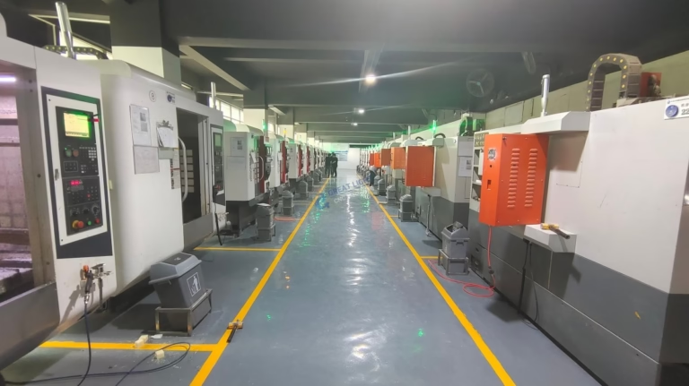
Capacity sets the process window. Our 127 high-precision CNC machines include 16 simultaneous 5-axis centers, 12 four-axis mills, 27 three-axis machines and 16 mill-turn centers. Maximum processing size reaches 4,000 mm, with travels of 4,000 × 400 × 150 mm on the large frames and 750 × 1,150 × 550 mm on the medium ones. The Ø400 mm rotary table handles the round work that would once have needed a second setup.
Inspection closes the loop on the shop side. We run raw material checks, in-process monitoring and final inspection, with 100% inspection before shipment and reports on request. That is how a control loop that started on a 28-ton retrofit mill ends up as a 99.99% qualification rate on a production run.
Materials and finishes are the last variables. Aluminum 6061-T6 and 7075, stainless 304 and 17-4PH, Ti-6Al-4V, Inconel and PEEK all cut differently, and the finish call (anodizing, electroless nickel, bead blasting, laser marking) has to be made before the last pass, not after.
- 15-axis and mill-turnFewer setups, fewer datum shifts, better feature access.
- 2ProbingCatches thermal drift and backlash mid-run, not at final inspection.
- 3DocumentationInspection reports on request for regulated industries.
NC, CNC and the Alternatives Compared
Use this when the question is which control era or which process fits the part.
| Factor | NC (punched tape) | CNC (stored program) | Better alternative |
|---|---|---|---|
| Program storage | Paper or magnetic tape | Controller memory | CAM file on a network |
| Change a dimension | Re-punch the tape | Edit the offset at the console | Not applicable |
| Typical tolerance | Loose, tape and reader dependent | ±0.005 mm on rigid setups | Grinding for tighter work |
| Best part count | One to a few | One prototype to 10,000+ | Die casting above that |
| Internal channels | Not possible | Only by splitting the part | 3D printing or casting |
| Setup time | Hours of tape prep | Minutes of fixture and probe | Press tooling for high volume |
| Surface finish | Coarse, chatter prone | Ra 0.2–0.8 μm achievable | Polishing after machining |
The verdict for your part
If you need repeated prismatic geometry at ±0.005 mm, CNC is the right process and the 1952 control loop is still doing the work. If your part is a one-off organic shell with internal channels, choose 3D printing or casting instead, and bring it to us only for the critical machined faces.
Questions engineers still ask
Was the first CNC machine built in 1952 or 1949?
The Parsons Air Force contract was awarded in 1949, but that funded development, not a finished machine. The recognized demonstration came in 1952, when MIT ran the retrofitted Cincinnati Hydro-Tel under numerical control.
So 1949 is the starting point of the program and 1952 is the first working NC contouring machine. Neither date describes a computer-controlled machine in the modern sense.
What is the difference between NC and CNC?
NC reads axis commands from a fixed medium such as punched tape or a plugboard. The logic is hard-wired and the program cannot be edited at the machine.
CNC stores the program in memory and runs it through a computer. Offsets, cutter compensation and canned cycles become software, so changeover takes minutes instead of a new tape.
Does the history matter for tolerances today?
Yes, because the control loop has not changed in principle. Position feedback, interpolation and servo response still set the accuracy ceiling on any machine.
A modern controller closes that loop thousands of times per second, which is why a 5-axis center can hold ±0.005 mm on a contoured surface.
Which parts should not be made on a CNC machine?
One-off organic shells, hollow conformal channels, and very high-volume simple parts. Those fit 3D printing, casting, or a press better.
Splitting a part to reach an internal channel adds a seam, a fixture and an assembly step, which usually costs more than the alternative process.
How do you hold tolerance across a long production run?
Warm-up cycles stabilize the spindle and ballscrew, reversal checks catch backlash, and in-process probing catches drift before the run ends.
We inspect 100% of parts before shipment and provide reports on request, with raw material checks and in-process monitoring upstream.
Can you machine a prototype and then a production run?
Yes. There is no minimum order quantity, so the same shop runs one prototype and then 10,000+ part runs.
Keeping the part on one process also keeps the datum scheme identical, so the prototype tells you something true about the production parts.
Send the drawing, get the DFM back in 12 hours
Upload your STEP file and we return a quotation with a free DFM analysis within 12 hours. Uploads stay secure and confidential, and an NDA is available on request.
12-hour quoteNo minimum order100% inspection
More from the shop floor
We publish setup notes, tooling trials and inspection data from the factory floor.











