
3 axis CNC milling explained
This page covers what 3 axis CNC milling actually does: how the X, Y and Z axes move, what tolerance and surface finish are realistic, and which part geometry suits the process. Written for design engineers, mechanical engineers and purchasing teams who have to pick a process before sending a drawing out for quote.
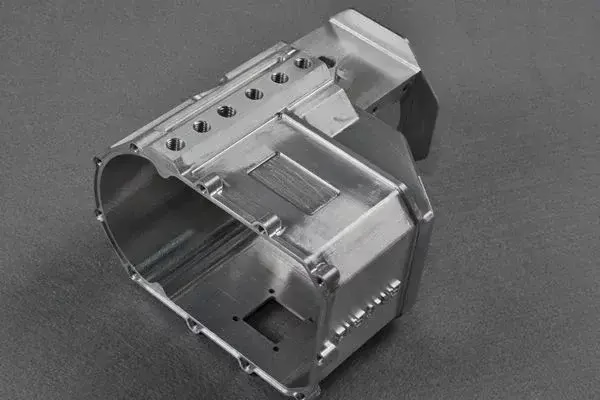
What this process is, in shop terms
Three linear axes, one spindle orientation, and a lot of parts that never need more than that.
How the three axes move and why it matters
A 3 axis machine has three linear axes at right angles: X, Y and Z. On a vertical machining center the spindle stays vertical, so the cutting tool always approaches the work from above. The table carries the workpiece in X and Y, the spindle head moves in Z, and the controller interpolates all three at once so the tool tip follows the CAM path.
That single approach direction is the whole story. Every feature you can cut without tilting the part is reachable. Pockets, slots, shoulders, stepped faces, drilled and tapped holes, contour profiles. If a feature sits on the side of the part or under an overhang, the setup has to be flipped or the feature has to wait for another process.
The controller runs G-code generated from a CAM system. Feeds, speeds, stepover and depth of cut come from the toolpath, and the machine repeats that path to within its positioning accuracy. The operator's job is the setup: workholding, zeroing, tool offsets, and checking that the first part matches the drawing.
- 1Vertical spindleTool axis stays parallel to Z. No tilt, no rotary table needed.
- 2Three simultaneous axesX, Y and Z interpolate together to cut curves and angles.
- 3One work orientationFeatures on other faces require a flip and a second setup.
Which parts suit it, and which do not
Prismatic parts with features opened to one direction are the natural fit. Plates, brackets, housings, manifolds with face-mounted ports, heat sinks, fixture plates, control panels, gearbox covers. These parts can be held flat on a vise or a fixture plate, cut from one side, and finished without ever repositioning the work.
Parts with features on five or six faces, deep cavities with undercut walls, or contoured surfaces that wrap around a cylinder are where the process starts to cost more, not less. You can still make them. It just takes more setups, more fixtures, and more chances for position error to stack up between operations.
The practical test is simple. Look at the drawing and count how many distinct tool approach directions the finished part needs. One or two, and 3 axis is usually the cheaper route. Three or more, and a 4 or 5 axis machine will often beat it on total cost once you account for fixtures and setup time.
- 1Good fitFlat-backed parts, one-sided features, simple holes and pockets.
- 2ManageableTwo or three faces, if the part can be re-fixtured accurately.
- 3Poor fitUndercuts, wrap-around contours, impeller blades, deep angled cavities.
Where 3 axis sits against 4 and 5 axis
Use this as a first filter before you request a quote.
| Criterion | 3 axis | 4 axis | 5 axis |
|---|---|---|---|
| Tool approach directions | One, from Z | Two or more with rotation | Continuous, any direction |
| Typical setups per part | 1 to 3 | 1 to 2 | 1 |
| Undercuts and side features | Needs a flip | Often reachable | Reachable |
| Fixturing cost | Low | Medium | Low to medium |
| Best for | Prismatic, one-sided parts | Cylindrical parts with flats | Complex contoured surfaces |
| Typical tolerance held | ±0.005 mm | ±0.005 mm | ±0.005 mm |
Tolerance, finish and what drives the number
On a well-maintained machine, ±0.005 mm is achievable on a 3 axis milling job, and we hold that across the 27 three-axis machines on our floor. That number is a target, not a default. It depends on the material, the feature size, the tool reach, and how rigid the setup is.
Surface finish follows the same logic. Ra 0.8–1.6 μm is a normal machined finish for aluminum and mild steel. Ra 0.2–0.8 μm needs a finer stepover, a sharper tool and often a finishing pass with a small nose radius. As-machined surfaces sit around Ra 1.6–3.2 μm and are fine for most brackets and covers.
Long tools deflect. A Ø6 mm end mill reaching 60 mm deep will chatter long before the machine's positioning error shows up. Thin walls move under clamping pressure. Deep pockets trap chips and heat. These are the real limits on a 3 axis job, not the axis count. If your drawing has a tight tolerance at the bottom of a deep pocket, expect the shop to ask about tool access before quoting.
- 1Feature sizeSmall internal radii need small tools, which deflect more.
- 2Tool reachAspect ratio above 5:1 starts to cost finish and tolerance.
- 3WorkholdingLoose setups move. Rigid fixtures hold the number.
Setup count, cycle time and cost per part
Cost in milling is mostly time and setups. A part that runs in one setup has one zero point, one fixture and one first-article check. Add a second setup and you add a fixture, a re-datum, and the risk that the two operations do not line up perfectly. That risk is the reason a 3 axis quote can climb fast on a part that looks simple on screen.
For low volume runs, 3 axis is usually the fastest way to a real part. No rotary table to program, no post-processor surprises, and standard vises and fixture plates handle most work. We run from one prototype to 10,000+ part runs with no minimum order quantity, and the same toolpath scales to a pallet setup for higher volume.
For high volume, the axis count matters less than the fixture. A well-designed tombstone or pallet fixture on a 3 axis machine can cut cycle time by keeping the spindle in the cut while the operator loads the next part. That is often cheaper than moving the job to a 5 axis machine.
Materials and finishes that pair well
Aluminum is the default for 3 axis work. 6061-T6 cuts clean, holds tolerance well, and takes anodizing without drama. 7075 is stiffer and used for aerospace brackets, but it is more abrasive on tooling. 2024 and 5052 behave differently again, mostly in chip formation and finish quality.
Stainless 303 and 304 are common, with 316L for medical and marine. They work-harden, so the toolpath has to keep a constant chip load rather than dwell in the cut. Steel grades like 1018, 1045, 4140 and 4340 mill fine if speeds and feeds are dialed in. Titanium Ti-6Al-4V and Inconel are machinable on a 3 axis machine but at much lower material removal rates, and they eat tool life.
Plastics like POM, PEEK, ABS and HDPE cut easily but need sharp tooling and air blast to clear chips. PEEK is the one to watch: it is expensive, abrasive to tooling, and sensitive to heat buildup. Finishes that pair well with 3 axis parts include anodizing, electroless nickel, zinc plating, powder coating, black oxide, bead blasting and laser marking.
Common questions from engineers
Can 3 axis milling hold ±0.005 mm on every feature?
No. It is achievable on well-supported features with short tool reach and a rigid setup. Deep pockets, thin walls and long tools will loosen that number.
Tell us which dimensions are critical on the drawing. We will flag anything that needs a different strategy before the job starts.
How do I know if my part needs 4 or 5 axis instead?
Count the tool approach directions on the drawing. One or two, and 3 axis is usually cheaper. Three or more, or any undercut that cannot be reached from above, and a rotary axis will likely save money overall.
A free DFM review will tell you which way we would quote it and why.
What is the largest part you can mill on three axes?
Our largest 3 axis travel is 4,000 × 400 × 150 mm. We also run 750 × 1,150 × 550 mm, 600 × 600 × 600 mm, 500 × 500 × 450 mm and 500 × 310 × 200 mm envelopes.
If your part is bigger than the largest envelope, it can often be split into sections and assembled, or moved to a different process.
What surface finish should I specify?
Ra 1.6–3.2 μm is a standard as-machined finish and is fine for most non-cosmetic parts. Ra 0.8–1.6 μm is a normal fine finish. Ra 0.2–0.8 μm needs a dedicated finishing pass and a sharp tool.
Over-specifying finish adds cycle time without adding function. Specify the coarsest finish that still meets the requirement.
Do you charge for a second setup?
Quotes are based on the actual work: setups, fixturing, cycle time and inspection. A part that needs three flips costs more than a part that runs in one.
We will show the setup count in the DFM notes so you can see where the cost sits.
What tolerances and materials can you inspect?
Every part gets 100% inspection before shipment: raw material check, in-process monitoring and final inspection. Reports are available on request.
We mill aluminum, stainless, carbon steel, alloy steel, copper and brass, titanium, Inconel, magnesium and engineering plastics.
Send a drawing and get a process answer
Upload your CAD file and we will return a quote plus a free DFM analysis within 12 hours, including a note on whether 3 axis is the right route for the geometry.
12-hour quote100% inspectionNo MOQNDA on request









