
4 axis CNC milling explained
This page covers how a fourth rotary axis changes the toolpath, the workholding, and the tolerance pattern on a milled part. It is written for design engineers and buyers comparing 3-axis, 4-axis and 5-axis routes. By the end you can tell whether your part belongs on a 4-axis machine.
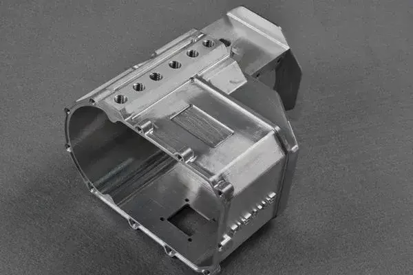
What the fourth axis actually adds
A 3-axis mill moves the tool in X, Y and Z. A 4-axis mill adds rotation, so the part turns while the cutter works.
How a fourth axis is mounted and indexed
A 3-axis vertical mill moves the spindle in X, Y and Z against a fixed part. Add a fourth axis and the part itself rotates. In most shops that axis is A, rotation about X, because X on a vertical mill is the long table direction. A trunnion-style rotary table clamps the part on a faceplate or between a chuck and a tailstock, so features on several sides can be cut in one setup.
Indexed 4-axis work stops at fixed angles. The table rotates to 90°, clamps, and the cutter machines that face. This is common for parts with pockets or bolt patterns on four sides. It is fast to program and rigid, since the table locks during cutting.
Continuous 4-axis work rotates while the tool is in the cut. A cylindrical boss, a cam profile, or a helical slot can be finished in one pass. The controller interpolates the A and X axes together, which is where the programming effort goes up and the cycle time usually goes down.
The rotary table on our 4-axis machines is Ø400 mm. That size sets the practical limit as much as the travels do. A part that swings past the table radius, or one that is long enough to whip when indexed, needs a different setup.
What changes in CAM for 4 axis cnc milling
The CAD model is the same model you would send for 3-axis work. The difference appears in CAM. A 3-axis toolpath assumes a single tool direction, so the software only has to avoid gouges in one orientation. With rotation in play, the tool axis moves relative to the part and the software has to keep the shank and holder clear the whole time.
For indexed work, the programmer creates several 3-axis setups inside one file and posts them with A moves between them. The post processor must output the rotation and the clamp command, then re-zero the work offset. Get that wrong and parts come out mirrored on the second face.
For continuous work, the operation is a surface or swarf path wrapped around the rotary axis. Feed rate becomes the hard part. The surface speed at the outside of a Ø120 mm boss is roughly four times the speed near a Ø30 mm hub, so a single feed value is either slow at the rim or too aggressive at the core. Most CAM tools let you drive feed from the rotary rate, but the programmer still has to check the result.
Stock models and fixtures have to be modeled too. A rotary table, chuck jaws and tailstock that are not in the CAM file will not appear in the simulation, and a collision that the simulation never saw shows up on the machine. We model the fixture for every 4-axis job.
3-axis, 4-axis or 5-axis: matching the part to the machine
Use this as a first filter before quoting. The middle column is where most cost-sensitive work lands.
| Part feature | Best route | Why |
|---|---|---|
| Flat plate, one face, through holes | 3-axis | No rotation needed; lowest setup cost |
| Holes or slots on four sides of a block | 4-axis indexed | One setup replaces three or four |
| Cam profile or helical slot | 4-axis continuous | A and X interpolate in one pass |
| Cylindrical part with radial ports | 4-axis indexed | Rotary indexing beats a manual indexer |
| Undercut on a contoured surface | 5-axis | Tool axis tilts to reach the back side |
| Impeller with twisted blades | 5-axis | Blade twist needs simultaneous tilt |
| Long shaft, features near both ends | 4-axis, tailstock | Rotation supports the part between centers |
| Deep cavity, straight walls | 3-axis | Rotation adds nothing to reach or finish |
Workholding and the tolerance pattern it creates
Rotation moves the part, so the fixture has to hold it against cutting force in every indexed position. A vise that is fine for one face may not be fine at 90°. Three-jaw chucks, collet blocks and dedicated tombstone fixtures are the usual answers. Which one you pick shows up in the drawing as concentricity and perpendicularity.
Concentricity is the number that changes most. When a part is turned in a chuck and indexed between operations, runout at the chuck becomes runout at the feature. We hold ±0.005 mm on 4-axis work, but the setup has to earn it. A part with a 200 mm overhang from the chuck will not hold that number at the far end without a tailstock.
Indexing repeatability matters more than absolute accuracy. If the table returns to 90° with a 0.01° error, a feature 100 mm from center moves about 0.017 mm. That is acceptable for most brackets and not acceptable for an optical mount.
Thermal drift is the quiet one. A rotary table that has been indexing for two hours is warmer than one that just started, and the center height shifts. On tight-tolerance runs we let the machine warm up and cut the first article after that, not before.
When 4-axis is the wrong call
A fourth axis is not free. It adds setup time, fixture cost and programming hours. If a part has features on two faces and the volume is low, two 3-axis setups are often cheaper. The break-even is usually around the third face or the first curved feature that would need a ball cutter run in several orientations.
Some geometry simply needs five axes. A deep undercut, a twisted blade, or a port drilled at an angle that the tool cannot reach without shanking out will not be solved by rotation about one axis. Forcing it onto a 4-axis machine means a special cutter or a second operation, and both cost more than the 5-axis hour would have.
Very large parts are another limit. Our 4-axis mills cover a Ø400 mm rotary table. A 4,000 mm part goes on a large gantry or a mill-turn center instead. Long shafts with features at both ends are usually better on a mill-turn machine, where turning and milling happen in one setup.
Finally, consider the finish requirement. Continuous 4-axis milling leaves a scallop pattern that follows the rotary path. If the drawing calls for Ra 0.2–0.8 μm across a curved surface, plan on a finishing pass at a fine stepover or a secondary polish. Bead blasting and polishing are available in-house.
Questions engineers ask before quoting
How do I know if my part needs 4 axis cnc milling rather than 3-axis?
Count the directions the tool has to approach from. If every feature is reachable from one face, 3-axis is enough. If the part has holes, slots or pockets on three or more sides, or a curved profile that wraps around a cylinder, 4-axis removes the manual re-fixturing.
The second test is tolerance. Every time a part is moved to a new fixture, the datum shifts. If two features on opposite faces must be concentric or perpendicular to each other within ±0.005 mm, cutting them in one 4-axis setup is the safer route.
Can a 4-axis machine cut a helical slot or a cam profile?
Yes, if the machine supports continuous rotation and the controller can interpolate the rotary axis with a linear axis. The cam or helix is programmed as a wrapped toolpath, and the part rotates while the cutter feeds along X.
The limit is the surface speed variation across the feature. On a large diameter change, feed has to be trimmed at the rim. We check this in simulation before the first cut.
What materials do you run on the 4-axis mills?
Aluminium 6061, 7075 and 6082; stainless 303, 304, 316L and 17-4PH; alloy steels such as 4140 and 4340; brass C36000 and copper C110; titanium TC4; and engineering plastics including POM, PEEK and PA.
Material choice changes the fixture as much as the cutter. A thin-walled aluminium part can be held in soft jaws, while a 17-4PH part with interrupted cuts needs a more rigid setup and a tailstock.
Does 4-axis milling cost more than 3-axis?
The hourly rate is higher because the machine and the programming are more involved. That premium is often recovered by removing two or three 3-axis setups and the inspection that goes with them.
For a small batch with features on two faces, 3-axis is usually cheaper. For a part with features on four sides, the 4-axis route wins on total cost, not on rate.
How is a 4-axis part inspected?
Inspection follows the same sequence as any milled part: raw material check, in-process monitoring, and final inspection before shipment. Reports are available on request.
For parts where the rotary indexing drives the critical dimension, we check the feature in the indexed position, not after the part is removed. That catches a fixture or offset error while the setup is still on the machine.
How long does quoting and production take?
Quotation and a free DFM analysis come back within 12 hours. Production can start within 24 hours of approval, and parts typically ship in 3–5 days.
There is no minimum order quantity. We run from one prototype to 10,000+ part runs, and uploads are handled as confidential with an NDA available on request.
Send the drawing and we will tell you which axis count it needs
Upload a STEP file and get a quotation plus a free DFM analysis within 12 hours.
12-hour quote100% inspectionNDA on requestNo minimum order









