
3D Printing and CNC Processing: Which One Fits Your Part
This guide compares additive and subtractive routes for engineers choosing between a printed prototype and a machined part. It covers tolerance, material behavior, surface finish and cost per unit at different volumes. Read it to decide when one process wins, and when running both makes sense.
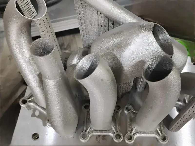
Two ways to reach the same geometry
Additive builds a part layer by layer. Subtractive cuts it out of solid stock. The difference drives every downstream decision.
Additive builds up, subtractive cuts down
Additive manufacturing starts from nothing and adds material. A nozzle, laser or binder deposits or fuses plastic, resin or metal powder one layer at a time. Internal channels, lattice cores and hollow shells cost almost nothing extra because they are just geometry the head never fills. Support structures are the tax you pay for overhangs and cavities.
Subtractive routes do the opposite. A cutter enters a solid block of aluminum, steel or titanium and removes everything that is not the part. Five-axis simultaneous motion lets the tool reach undercuts and compound angles in one setup. The stock you pay for is the stock you throw away, so nested layouts and short tool paths matter for cost.
The two methods rarely compete on the same feature. A printed impeller can have a twisted internal cooling passage that no end mill can reach. A machined hydraulic manifold holds a sealing face flat to ±0.005 mm and takes 200 bar without weeping. Pick the process that matches the critical feature, not the whole part.
What each process can actually run
Printing covers a wide but shallow material range. FDM handles ABS, PC, PETG and filled nylon. Resin systems give fine detail for fixtures and visual models. Metal powder bed fusion works with Ti-6Al-4V, Inconel 718, 316L and some aluminum alloys, but the alloy menu is short compared with wrought stock and each powder has its own laser parameters.
CNC processing draws from mill-certified bar and plate. We machine 6061 and 7075 aluminum, 303 and 316L stainless, 17-4PH, 4140 and 4340 steel, C360 brass, beryllium copper, TA2 and TC4 titanium, plus engineering plastics like POM, PEEK and HDPE. Material certificates travel with the parts.
That range matters when a part must pass a spec. A printed bracket in PA12 has no wrought equivalent, so you cannot cite 6061-T6 temper or a heat-treat lot. Machined stock carries traceability from the mill heat to the finished part, which is what aerospace and medical buyers ask for first.
- 1Printed metalsTi-6Al-4V, Inconel, 316L, some Al alloys. Short menu, powder-specific params.
- 2Machined metalsAluminum, stainless, steel, brass, copper, titanium. Mill certs available.
- 3Printed plasticsABS, PC, PETG, PA, resin. Good for fit checks and light fixtures.
- 4Machined plasticsPOM, PEEK, HDPE, PMMA, carbon fiber. Tight tolerance, real threads.
Tolerance and surface finish side by side
Layer lines, thermal shrinkage and support scars set the floor for as-printed accuracy. Industrial systems land around ±0.005 in on a good day, and thin walls warp more than the datasheet suggests. A sealing groove or bearing bore printed to nominal will usually need reaming or sanding before it fits.
Machining holds ±0.005 mm on critical features when the setup is rigid. Surface finish runs Ra 0.2–0.8 μm on a fine pass, Ra 0.8–1.6 μm on a standard pass, and Ra 1.6–3.2 μm as machined. That usually removes any need for grinding or polishing on mating faces.
The gap is widest on fits. A printed shaft for a 10 mm bearing will be undersized or oversized depending on orientation and cooling. A turned shaft holds the press fit you drew. For anything that seals, spins or slides, subtractive wins.
Process comparison at a glance
Numbers below reflect typical industrial equipment, not prototypes on a desktop.
| Factor | 3D printing | CNC processing |
|---|---|---|
| Typical tolerance | ±0.005 in | ±0.005 mm |
| Surface finish | Ra 3.2 μm or rougher | Ra 0.2–1.6 μm |
| Material range | Narrow, alloy-specific | 100+ metals and plastics |
| Setup cost | Low, no fixturing | Higher, fixturing and CAM |
| Cost per unit at 1 pc | Low | Moderate |
| Cost per unit at 1,000 | High | Low |
| Internal channels | Complex, near free | Limited by tool reach |
| Material certs | Powder lot only | Mill heat lot |
| Post-processing | Often required | Minimal |
| Best fit | Prototypes, lattices | Functional end-use parts |
Where the cost curves cross
At one piece, printing usually costs less. There is no fixture, no CAM programming and no stock to buy. A resin or FDM bracket can be in your hand the next morning. For a fit check or a fascia model, that is the whole job.
The curve flips as volume rises. Print time scales with part height and layer count, so a batch of 200 is 200 separate builds unless you run a large bed. CNC time scales with material removed, and a well-programmed run of 200 parts spreads setup over the whole lot. At 10,000+ pieces, machining is usually the cheaper route.
Speed is not one number. Printing wins on the first article. Machining wins on the tenth revision, because you just reload the program. For a bridge to production, printed parts let you test form while the machined tooling and fixtures are still being made.
Matching the process to the job
Choose printing for form and fit checks, complex internal channels, lattice structures, low-stress brackets, jigs and visual models. It is also useful for small runs where tooling cost would dominate the budget and the load is light.
Choose CNC processing when the part carries load, seals a fluid, spins at speed or must hold a tolerance across a batch. Surgical instruments, turbine blades, engine mounts, hydraulic manifolds and bearing housings are machined for good reasons: material properties, surface integrity and inspection data.
Some parts use both. Print a conformal-cooling insert, then machine its mating faces. Print a lightweight frame, then ream the bearing bores. The two processes are complementary, not competing, and a mixed route often beats either one alone.
Common questions
Can a printed part be used as an end-use component?
Yes, for light loads and non-critical fits. Printed brackets, covers and ducting work in many products.
No, when the part seals, spins, carries fatigue load or must meet a material spec. Those cases need wrought stock and machining.
How tight can CNC processing hold on a complex profile?
We hold ±0.005 mm on critical features using simultaneous five-axis motion. That covers compound angles, undercuts and contoured sealing faces.
Fine passes reach Ra 0.2–0.8 μm, which usually removes the need for secondary grinding or polishing.
Which is faster for a first article?
Printing is usually faster for the first piece because there is no fixture or CAM programming.
Machining catches up on revisions. Once the program exists, a new version is a reload and a re-cut.
Do you support hybrid projects that combine both?
Yes. We run printed prototypes alongside machined end-use parts, and we machine printed components where a critical face needs to be flat or reamed.
One quote covers both routes, so you can compare cost and lead time before committing.
What about material traceability?
Machined parts ship with mill certificates on request, traced from heat lot to finished part.
Printed metal parts carry powder lot documentation, which is the limit of what the process offers.
How do you handle confidential designs?
Uploads are secure and confidential. We sign an NDA on request before reviewing drawings.
Our quality system is certified to ISO 27001:2022 for information security.
Send your drawing, get a process recommendation
We review your part, tell you whether printing or machining fits better, and quote both if the answer is close.
12-hour quoteFree DFM analysis100% inspectionNDA on request









