
3D Printing Master Chief Armor: 7 Costly Mistakes to Avoid
A build guide for cosplayers, prop makers and engineers who want a wearable suit, not a shelf ornament. It covers print orientation, material selection, post-processing budgets, fitment tolerances, support damage, shrinkage and reinforced mounts. After reading it you can decide which parts to print, which to machine, and where the two should meet.
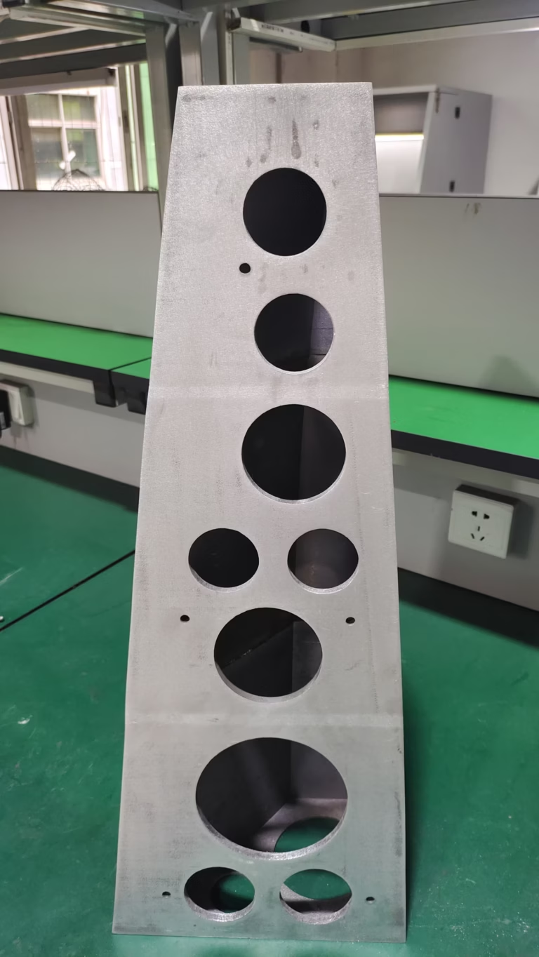
Where Master Chief armor builds go wrong
Most failed suits do not fail at the printer. They fail at the decisions made before the first layer went down.
Print orientation and layer-line strength
FDM parts behave like a stack of glued sheets. Along the XY plane the extruded roads bond side by side, and the part handles tension and bending well. Across the Z axis you only have the bond between one layer and the next, which is a fraction of that strength. For 3d printing master chief armor, every load path matters: crotch plates, shoulder straps, snap-fit tabs and the webbing anchors all pull across layers if you orient them badly.
The common failure is cosmetic orientation. A chest plate rotated so the front face prints smooth ends up with its rear mounting bosses printed on weak inter-layer bonds. During a first test fit, the boss shears off. Slicer auto-orientation does not help here because it optimizes support volume and surface quality, not load direction.
Do a manual pass instead. Mark the two or three highest-stress features on the model, then rotate the part so those features run in-plane with the layers. If a strap tab must take a pulling load, rotate it 90° even if the visible surface gets more support scars. Sanding hides scars. Nothing hides a snapped tab at a convention.
- 1Load-bearing tabsPrint in-plane so tension runs along the extruded roads, not across layer bonds.
- 2Cosmetic facesAccept extra support marks on hidden or sandable surfaces.
- 3Auto-orientationUse it as a starting point, then override it for stress features.
Picking material by print difficulty, not environment
PLA prints easily and looks good straight off the bed, which is why so many helmets start there. It also softens near 60 °C (140 °F). A black helmet left in a parked car on a sunny day can sag out of shape before you get back. Con halls are warm, humid and crowded, and outdoor photo shoots add direct sun. PLA is the wrong answer for a suit that leaves the house.
PETG is a reasonable middle ground. It tolerates higher temperatures, takes impacts without shattering and prints on most open-frame machines. It strings more, so budget extra cleanup time on thin details. ASA and ABS hold up better outdoors and take sanding and filler primer well, but they need an enclosure to control warping.
Resin (SLA) gives the smoothest surface for small, detailed pieces such as helmet greebles or shoulder emblems. It is brittle under impact, so keep it away from parts that flex or hit the ground. A mixed-material suit is normal: PETG or ASA for large shells, resin for small detail, machined aluminum for the joints that take real load.
- 1PLAFine for display pieces. Avoid for worn suits and hot cars.
- 2PETGGood impact resistance and moderate heat tolerance for large shells.
- 3ASA / ABSBetter UV and heat performance, but enclosure required.
- 4SLA resinBest detail, low impact strength. Small parts only.
Matching print material to armor function
Thin walls and large flat panels behave differently from small brackets. Use this as a first filter, not a final answer.
| Part type | Printed material | Why it works |
|---|---|---|
| Helmet shell | PETG or ASA | Takes heat and knocks, sands well |
| Chest plate | PETG, 4 mm walls | Stiff enough without heavy infill |
| Small greebles | SLA resin | Fine detail, low load |
| Strap tabs | PETG, in-plane | Flexes instead of snapping |
| Hip and knee joints | Machined 6061-T6 | Predictable load path, no creep |
| Threaded mounts | 303 stainless inserts | Repeated assembly without stripping |
Underestimating post-processing time
An 18-hour helmet print is not the job. It is the start of the job. FDM layer lines need filler primer, sanding, more filler, more sanding, then a base coat. On a full suit that manual work often runs past 100 hours, and most of it is repetitive rather than skilled. Plan the hours before you commit to the build, not after.
Resin parts skip the layer-line fight but add washing, post-curing and careful support removal. Even then, most users still apply a sandable primer to hide stepping on curved surfaces and to give the topcoat something to bite.
There is a shortcut that works: split the suit by function. Print the large organic shells that a mill cannot easily reach. Then machine the flat plates, joint blocks, buckle hardware and mold masters. A machined aluminum master can be polished to near-mirror finish, so the surface work drops from days to hours. Five-axis work also gives you draft angles and parting lines that a printed master cannot hold as cleanly.
- 1FDM suitBudget filler, primer and sanding time per panel, not per suit.
- 2Resin partsAdd wash, cure and support removal to the schedule.
- 3Machined mastersFlat plates and joints arrive close to final finish.
Ignoring assembly tolerances and fitment
Two printed halves that look correct in CAD can bind or gap on the bench. FDM dimensional error commonly runs a few tenths of a millimeter, and it changes with wall thickness, cooling and part size. If you design a 0.2 mm slip fit and the printer adds 0.3 mm, the joint will not close.
Design clearance in from the start. For printed-to-printed joints, leave 0.3–0.5 mm per side on sliding fits and test with a small coupon before printing a full panel. For printed-to-machined joints, hold the printed side loose and let the metal side define the fit. Machined parts can hold ±0.005 mm, so they are the reference, not the printed shell.
Body fit is a separate problem. Armor worn over a soft under-suit needs roughly 10–20 mm of clearance at the chest and thighs for movement, and hard edges near the shoulders and hips should be rounded or padded. Print a small section of the torso first and wear it for ten minutes before committing to the full set.
- 1Printed-to-printedUse 0.3–0.5 mm per side and verify with a test coupon.
- 2Printed-to-machinedLet the metal part set the fit; keep the print loose.
- 3Wear clearanceAllow 10–20 mm at chest and thighs for movement.
Support damage and shrinkage you did not plan for
Supports leave three kinds of damage: pits where the tip touched, scars where the interface layer bonded too hard, and gouges when the removal tool slips. On thin armor panels, a gouge can go through the wall. Tune the Z distance and interface density on a test piece, and cut supports with flush cutters instead of pulling them off by hand. On resin parts, remove supports before the final cure while the material still has some give.
Shrinkage is the other quiet failure. Large flat panels warp as the upper layers cool faster than the lower ones, and the whole part can come out undersized. ABS and ASA shrink more than PETG, and a 300 mm panel can lose several millimeters across its length. If two printed halves must meet, add a shrinkage allowance in the slicer or scale the model, and keep the build chamber warm and draft-free.
For anything that has to stay flat, consider machining the panel instead. A 6061-T6 plate cut flat stays flat, and you can hold ±0.005 mm across a 4,000 mm envelope if the part needs it. Warping stops being a variable.
- 1Support tipsTune Z distance on a coupon before a full panel.
- 2Resin supportsRemove before final cure to reduce chipping.
- 3ShrinkageAdd allowance for large panels, especially ABS and ASA.
Skipping metal inserts and reinforced mounts
Printed threads are the weakest feature on any armor build. A screw driven into a printed boss strips after two or three assembly cycles, and the boss cracks along a layer line. Heat-set brass inserts help, but they still sit in a polymer wall that creeps under load.
The parts that fail are predictable: helmet hinge pivots, shoulder strap anchors, belt buckles, knee joint pins and anything carrying the weight of the suit. These are small, simple shapes, which makes them good candidates for machining. A 6061-T6 aluminum bracket or a 303 stainless insert takes repeated assembly, holds a real thread and does not soften in a hot car.
A useful rule: print the shape, machine the interface. Shells stay printed because they are large and organic. Mounts, pivots, hinge plates and threaded bosses get machined. The cost per part is modest, and it turns a suit that lasts one season into one that survives several.
- 1Heat-set insertsBetter than printed threads, still limited by the polymer wall.
- 2Machined brackets6061-T6 or 303 stainless for pivots and anchors.
- 3Rule of thumbPrint the shape, machine the interface.
Questions engineers ask before printing a suit
How thick should FDM armor walls be for a wearable suit?
For a chest plate or back panel, 3–4 mm walls with two or three perimeters give a good balance of stiffness, weight and print time. Thin shells under 2 mm flex too much and crack at layer lines under impact.
Local thickness matters more than average. Add ribs or bosses at mounting points rather than thickening the whole panel.
Can I print the whole suit and skip machining entirely?
You can, but the failure points will be the same ones every time: hinge pivots, strap anchors and threaded bosses. These are small parts where machining is cheap relative to the printing and finishing time already spent.
A hybrid build is usually faster overall because machined plates and joints need almost no surface work.
What tolerance can I expect on printed armor parts?
Desktop FDM typically lands within a few tenths of a millimeter on small features, and worse on long panels because of shrinkage and warping. That is fine for cosmetic shells and not fine for joints or mating faces.
When a printed part must meet a machined one, let the machined part set the fit. Our machining holds ±0.005 mm, so the printed side can stay loose and be packed or clamped.
Which parts are worth machining instead of printing?
Hinge plates, shoulder anchors, buckle hardware, knee pins and any threaded interface. These are simple prismatic shapes with real load paths, so a 5-axis cut is quick and the result does not creep.
Machined mold masters are another option if you plan to reproduce panels in resin or vacuum casting.
How do I stop large flat panels from warping?
Keep the chamber warm and free of drafts, use a brim, and lower the cooling fan on the first layers. For ABS and ASA, add a shrinkage allowance because a 300 mm panel can lose several millimeters.
If flatness is critical, machine the panel from 6061-T6 plate. Flat stays flat.
What finishes work on machined armor hardware?
Anodizing in clear, color or hardcoat suits aluminum brackets and plates. Bead blasting gives a matte, non-reflective look that matches many armor finishes.
Black oxide and electroless nickel are options for steel and stainless inserts. Laser marking works down to 1.5 mm character height if you want part numbers on internal hardware.
Send us the parts you would rather not print
Upload your hinge plates, brackets and inserts. We return a quote and a free DFM review within 12 hours, and every part is inspected before it ships.
12-hour quote±0.005 mmNo minimum orderNDA on request









