GreatLight CNC Machining Factory logo
CNC Machining
Rapid Prototyping
Materials
Industries
News
About GL

Get Instant Quote

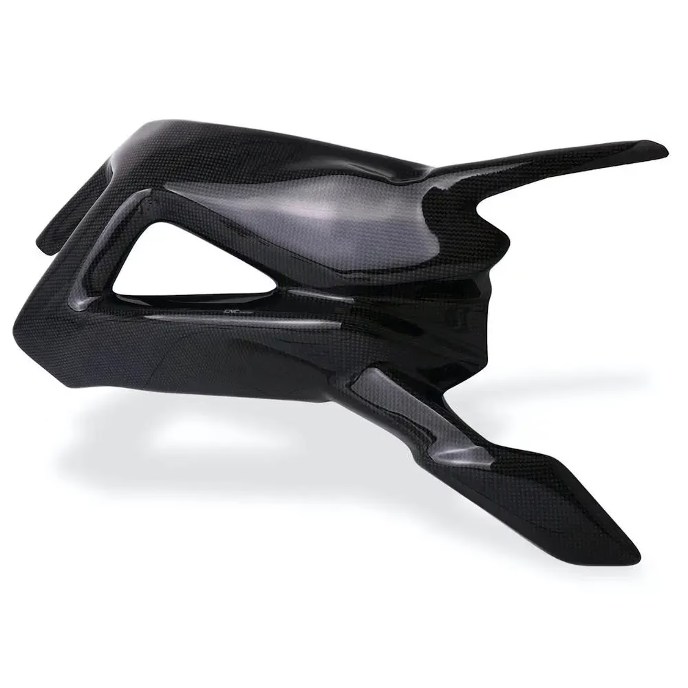
Carbon Fibre Additive Manufacturing

3D Priting Carbon Fibre Parts

We print chopped and continuous carbon fibre reinforced parts, then machine the critical faces on the same floor when the print alone cannot hold the tolerance. Send a model and we will tell you which process fits.

Carbon fibre reinforced nylon±0.005 mm on machined facesNo minimum orderQuote in 12 hours
cnc-carbon-fiber
15 yearsAdditive and subtractive work under one roof
127High-precision CNC machines on site
±0.005 mmTolerance on machined interfaces
99.99%Qualification rate before shipment
Where printed parts fail

Four Problems Engineers Bring to Us

Most reinforced print jobs that stall on the desk fail for one of these reasons.

01

The print grows overnight

A flat panel printed on a heated bed warps after cooling. Bolt holes no longer line up with the mating plate, and the whole batch is scrap. Fibre loading helps stiffness but makes warp worse when the print orientation is wrong.

02

Layers split at the load point

Chopped fibre raises stiffness in the XY plane. Pull on the part along Z and the bond between layers is still resin. A bracket that tests well in one direction will crack in the other.

03

Tolerance is stated but never met

A drawing asks for ±0.1 mm on a bearing bore. The printer holds that on a good day and drifts on a bad one. Nobody can tell you which day you got until the parts arrive.

04

Prototype dies before production

The printed part proves the design, then the mould quote comes back with a lead time that kills the schedule. You need a bridge batch that behaves like the final part and ships now.

How we build it

Print the Geometry, Machine the Interfaces

One shop floor handles both steps, so nobody argues about who owns the tolerance.

oplus_262178
Process choice

Pick the print process from the load case, not the brochure

Chopped carbon fibre nylon suits brackets, housings and fixtures where stiffness matters more than surface finish. Continuous fibre layup gives higher strength along a known load path, and we route the fibre where the FEA says it belongs.

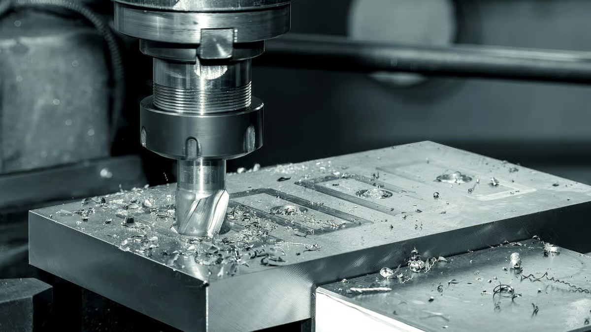
When a bore, a seal face or a mating surface needs metal-level tolerance, we print oversize and cut it back on a 3-axis or 5-axis mill. That removes the layer stair-step and gives a true datum.

  • 1
    Chopped fibre nylonStiff, light, good for brackets and jigs up to about 200 mm
  • 2
    Continuous fibre layupDirectional strength along a defined load path
  • 3
    Hybrid print and machinePrinted blank, machined bore, face or thread

Get Instant Quote

CNC Lathe Technical Specifications Terminology
Finishing

Post-processing decides whether the part survives the field

As-printed surfaces hold moisture and show layer lines. We bead blast, prime and paint, or apply a metal coating when the part needs EMI shielding or a wear face. Small features get masked so threads and bores stay functional.

For low-volume runs we also finish on the CNC side: anodizing, powder coating and laser marking are all handled in house. That keeps one drawing, one inspection report and one shipping date.

  • 1
    Bead blasting and paintingRemoves layer lines, seals the surface
  • 2
    Metal coatingConductive layer for shielding or wear
  • 3
    Laser markingPart numbers and revision codes, minimum 1.5 mm character height

Talk to an Engineer

Selection guide

Which Route Fits Your Part

Use this when the drawing could go two ways.

RequirementPrinted carbon fibre partPrinted blank plus CNC
Overall tolerance±0.3 mm typical±0.005 mm on cut faces
Surface finishVisible layer linesRa 0.8–1.6 μm on machined areas
Load directionBest in XY planeSame, plus true bores and datums
ThreadsCoarse, printed or insertedCut threads, full depth
Typical sizeUp to 200 mmUp to 4,000 mm travel
Best forBrackets, covers, jigsHousings, bearing seats, seals
What we run

Services Around Carbon Fibre Parts

One supplier for the print, the machining and the finish.

01

Custom 3D Printing

Chopped and continuous fibre parts, printed to your model, with print orientation chosen for the load case.

02

Rapid Prototyping

A functional prototype in days, not weeks. Same material family as the production part so test data carries over.

03

5 Axis CNC Machining

16 simultaneous 5-axis centers cut compound angles, bores and pockets on printed blanks.

04

CNC Milling & Turning

Mill-turn centers handle round features and prismatic cuts in one setup to protect datums.

05

Part Surface Finishing

Painting, metal coating, bead blasting and laser marking, all with inspection records.

06

Sheet Metal & Vacuum Casting

When the part is better as formed metal or a cast urethane copy, we say so and quote that instead.

Capability

Shop Capacity at a Glance

ItemSpecification
Machines on site127 high-precision CNC machines
5-axis centers16 simultaneous 5-axis machining centers
Maximum part size4,000 mm processing length
Large travel4,000 × 400 × 150 mm
Rotary tableØ400 mm
Tolerance±0.005 mm (±0.0002 in)
Fine finishRa 0.2–0.8 μm
Order sizeOne prototype to 10,000+ parts
Quote turnaroundQuotation and free DFM within 12 hours
Why GreatLight

Six Reasons Engineers Keep Sending Files

15Y

Fifteen years in business

Founded in 2011. Three wholly-owned plants in Dongguan and a factory in Singapore, covering 7,600 m².

127

Machines under one roof

Printing, 5-axis milling, turning and finishing sit on the same floor, so the print-to-cut handoff takes hours.

±0.005

Tolerance we will sign for

Machined interfaces hold ±0.005 mm. Fine finishes run Ra 0.2–0.8 μm when the drawing calls for it.

12 h

Quote and DFM feedback

Send a model and you get a quotation plus a free DFM analysis within 12 hours. Production can start in 24 hours.

99.99%

Qualification rate

Raw material check, in-process monitoring and final inspection. Reports on request.

1 to 10,000

No minimum order

One prototype or a 10,000-part run. The process changes, the inspection standard does not.

7,600 m²Manufacturing space
150Technicians on staff
3–5 daysTypical shipping after start
<2%Historical late-delivery rate

Industries and parts

Where These Parts Go

Leader in Cnc Machining Service China

Aerospace brackets

Lightweight reinforcement ribs, printed then faced flat.

  • ±0.005 mm datums
  • IATF 16949
CNC Machining Services Online

Automotive fixtures

Carbon fibre jigs that resist weld heat and stay flat.

  • Ra 0.8–1.6 μm
  • 100% inspection
6011

Robot end effectors

Stiff arms in chopped fibre, machined tool plate.

  • No minimum order
  • 3–5 day ship
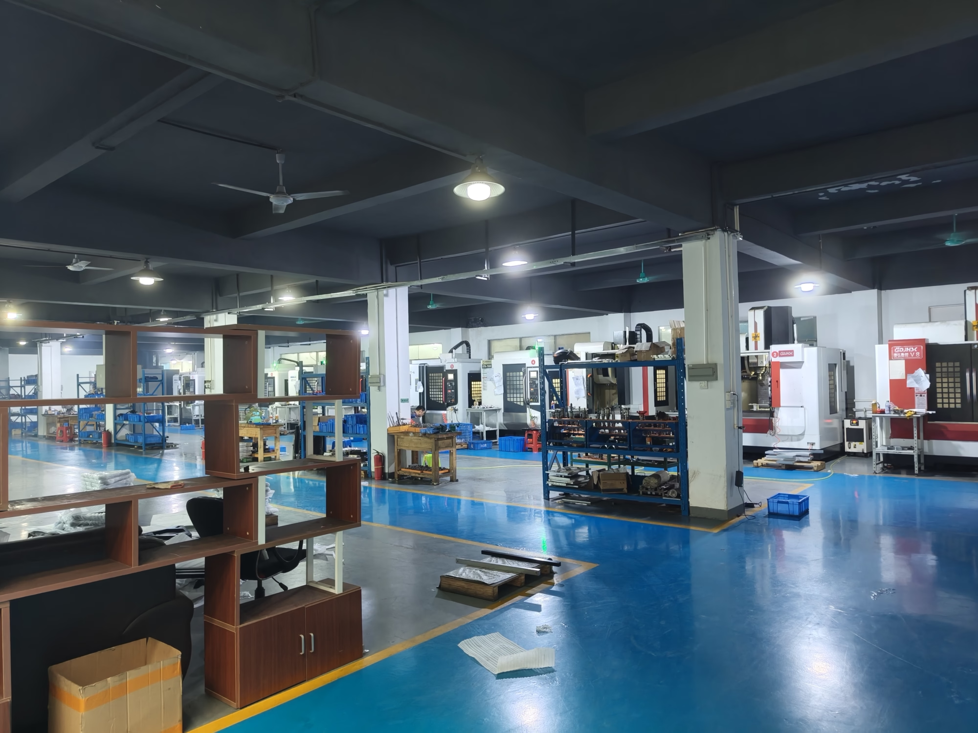
GreatLight Metal new factory building

Medical housings

Dimensional stability over repeated sterilisation cycles.

  • ISO 13485
  • ISO 9001:2015
FAQs

Questions We Get Every Week

When is a printed carbon fibre part the wrong answer?

If the part sees continuous load above roughly 80 °C, or takes impact along the layer direction, a printed polymer part is the wrong choice. We would quote machined aluminium or a compression-moulded part instead.

Another sign: the drawing needs a thread deeper than twice the diameter, or a sealing face below Ra 0.8 μm. Those features want metal or a machined insert.

How do you stop a large flat part from warping?

Orientation and support strategy do most of the work. We print long panels on edge where the machine allows it, add a stiffening rib pattern in the model, and let the part cool in the chamber before it leaves the plate.

If it still moves, we print oversize and face both sides on the mill. That costs one extra setup and saves the batch.

What tolerance can a printed surface hold?

As-printed geometry typically lands around ±0.3 mm on a 200 mm part, and it varies with wall thickness and fibre loading. Treat that as a starting point, not a specification.

Any face we machine holds ±0.005 mm. If one dimension matters, put a machining allowance on it and we will cut it.

Can you add threads and inserts?

Yes. We cut threads directly into the printed wall when there is enough material, or install a heat-set or moulded-in insert when the wall is thin.

Tell us the fastener and the torque. That decides whether a printed thread is safe or an insert is required.

Do you need a STEP file?

STEP is best. Native CAD also works, and STL is acceptable for simple parts where the surface does not matter.

Send the drawing with it. Tolerances, datums and finish callouts live there, not in the model.

How fast can you turn a job around?

Quotation and free DFM analysis come back within 12 hours. Production can start within 24 hours of approval, and parts usually ship in 3–5 days.

Large panels or multi-setup machined blanks take longer. We tell you the real number with the quote.

Is my design kept confidential?

Uploads are secure and confidential. We sign an NDA on request before any file is opened.

Our quality system is certified to ISO 27001:2022 for information security.

What materials do you also machine?

Aluminium 6061, 7075 and 2024; stainless 303, 304, 316L and 17-4PH; titanium TC4; engineering plastics including PEEK, POM and PC.

If the part belongs in metal, we will say so at the quote stage rather than printing something that fails in test.

Send the Model, Get a Quote in 12 Hours

Upload your file and we will come back with a price, a process recommendation and a free DFM analysis.

12-hour quote100% inspectionNo minimum order

Trusted by engineers and manufacturers worldwide

Tesla Ford Motor Company BYD Auto Denso Magna International Boeing Airbus Medtronic KUKA FANUC