
5 Essential 3D CNC Cutting Techniques to Maximize Precision and Cut Costs
Five toolpath strategies that decide whether a 3D part comes off the machine on tolerance and on budget. Written for design engineers and sourcing engineers who review CAM plans with their supplier. After reading, you can tell which technique fits a given cavity, wall thickness and material.
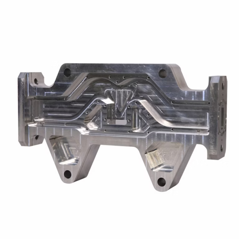
Five toolpath strategies, one cost question
Every technique below trades one variable against another: tool load, setup count, cycle time or hand finishing. The right choice depends on the geometry in front of you, not on a preference for one method.
Trochoidal milling: control the radial engagement, not the speed
Trochoidal milling replaces a straight full-width cut with a looping path. The cutter advances along a circular arc while stepping forward, so the radial engagement angle stays small and roughly constant. Chip load stays even, and the tool never buries its full diameter in the material.
That constant engagement is what protects the tool. Heat leaves with the chip instead of soaking into the edge, and the axial depth can be pushed deep while the radial width stays light. On stainless and titanium, this is often the difference between one tool per cavity and three.
The trade-off is path length. A trochoidal cycle covers more distance than a conventional pass, so it pays off on deep pockets and hard alloys where tool changes dominate the cost. In soft aluminium with shallow pockets, a conventional pass is usually faster. We pick trochoidal when the depth-to-diameter ratio climbs above roughly 2:1 or when the material is above 30 HRC.
- 1Best forDeep cavities, hardened steel, titanium and stainless where tool wear drives cost.
- 2Skip it whenThe pocket is shallow and the material is free-cutting aluminium.
Adaptive clearing: constant chip load from start to finish
Adaptive clearing is a CAM strategy, not a cutter. The software reads the remaining stock at each step and bends the toolpath so the engagement angle stays inside a target band. Corners get rounded off automatically, which avoids the sudden load spike that snaps small end mills.
The practical gain shows up in two places. Roughing passes can run at higher feed because the load is predictable, and the stock left for finishing is far more even. Uneven stock is what forces finishing tools to slow down, so a clean roughing pass lifts the whole cycle.
Adaptive clearing suits 3D surfaces where the stock varies a lot from the casting or the previous operation. It is less useful on a simple rectangular block, where the stock is already uniform and the extra path calculation buys little. On one aluminium 6061 housing we produce for robotics, switching the roughing cycle to adaptive clearing trimmed the cycle time without touching the finishing strategy or the tolerance.
- 1Best forCastings, forgings and near-net shapes with uneven stock.
- 2Watch forVery small tools in deep corners still need a reduced engagement target.
Five-axis simultaneous machining: fewer setups, tighter true position
Each setup adds a datum shift. Clamp a part four times and you stack four small errors, plus the operator time to re-fixture between them. Five-axis simultaneous work machines angled faces, undercuts and compound radii in one clamping, so the datums never move.
This is the technique that decides true position on parts with features on several planes. Aerospace brackets, medical housings and engine components often carry position tolerances that a three-axis sequence cannot hold reliably, no matter how careful the operator is.
Simultaneous motion is not the same as 3+2 positioning. In 3+2 the table indexes and locks, then cuts in a fixed orientation. Simultaneous work keeps all axes moving through the cut, which is what allows a single continuous pass over a compound surface. It costs more programming time, so we reserve it for geometry that genuinely needs it. A part with flat faces at fixed angles is usually cheaper as 3+2.
Our shop runs 16 simultaneous five-axis machining centers with a Ø400 mm rotary table, on travels up to 4,000 × 400 × 150 mm. That covers most brackets and housings in one operation.
- 1Best forFeatures on multiple planes, compound angles, undercuts, thin walls.
- 2Cost checkFlat faces at fixed angles are cheaper as 3+2 than simultaneous.
Peeling and plunge roughing: deep cavities without chip pile-up
Plunge roughing cuts downward with the end of the tool instead of the side. A relieved cutter or a button insert tool drops into the material in overlapping strokes, then steps over. Chips fall clear because gravity works with you, not against you.
The advantage is rigidity. A plunging tool bends far less than a side-cutting tool at the same overhang, so deep cavities hold straighter walls. In hard materials and on tall thin ribs, that stiffness is what keeps the part in tolerance.
Peeling takes the opposite approach. The tool engages a short axial depth and a large radial width, peeling material away in horizontal layers. It moves a lot of metal per minute and leaves a stepped floor that a finishing pass cleans up.
Neither method is a general-purpose roughing choice. Plunge roughing leaves a scalloped floor and works best on deep, open pockets. Peeling needs a rigid setup and a machine with enough spindle torque to push a wide radial cut. On a tall thin-wall part, both can pull the wall out of shape, so we switch to a light trochoidal path instead.
- 1Best forDeep open pockets, hard alloys, tall ribs that need a stiff cutter.
- 2Avoid onThin unsupported walls, where the cutting force deflects the part.
Corner picking and rest machining: remove the hand work
A large roughing tool cannot reach into a sharp internal corner. The leftover material there is called rest stock, and if nobody removes it in the machine, someone removes it with a file. That is where cost creeps back in after a clean cycle.
Rest machining tells the CAM system to calculate only the areas the previous tool missed. A smaller cutter follows that boundary, then an even smaller one follows the next. Each pass removes the minimum material, which keeps the small tools alive.
Corner picking finishes the job by matching the corner radius to the tool radius on the drawing. If the drawing calls for a sharp internal corner, no round tool can produce it, and the design needs a relief or an EDM step. Catching that at the quoting stage is far cheaper than catching it at inspection.
Used together, these two passes often remove hand deburring and benching from the route. That matters most on mould inserts and on parts with many pockets at different depths, where the stock left by the roughing tool varies from pocket to pocket.
- 1Best forMulti-pocket parts, mould inserts, deep corners after a large roughing tool.
- 2Design noteA sharp internal corner needs a relief or EDM; a round tool cannot cut it.
Matching the technique to the part
Use this table at the quoting stage to check whether the proposed strategy fits the geometry.
| Part condition | Technique to ask for | Why |
|---|---|---|
| Deep pocket, depth over 2× diameter | Trochoidal milling | Light radial engagement keeps the tool from snapping. |
| Uneven stock from casting or forging | Adaptive clearing | Constant chip load evens out the finishing allowance. |
| Features on several planes | Five-axis simultaneous | One clamping holds true position across all faces. |
| Flat faces at fixed angles | 3+2 positioning | Cheaper to program than simultaneous motion. |
| Deep open cavity, hard alloy | Plunge roughing | Axial cutting is stiffer than side cutting at long reach. |
| Sharp internal corner on drawing | Corner picking plus relief | A round tool cannot cut a zero-radius corner. |
| Thin wall, tall rib | Light trochoidal pass | Low radial load limits part deflection. |
Where precision and budget usually go wrong
The most common failure is choosing the roughing strategy before looking at the finish requirement. A fast roughing cycle that leaves 0.8 mm of uneven stock forces the finishing tool to slow down and can push a wall out of tolerance. Rough and finish have to be planned as one route.
Second is over-using simultaneous five-axis. It is a capable technique, and it is also a slow one to program. When the geometry does not need continuous motion, the programming hours go onto the part price without improving the result.
Third is ignoring tool reach. A long, thin cutter deflects under load, and no CAM setting removes that. If a deep cavity needs a long tool, plan a lighter stepover and accept a slower cycle, or redesign the cavity so a shorter tool can reach it.
Fourth is leaving rest stock for the bench. Hand finishing is the least repeatable operation in the shop. Moving that work into the machine keeps the process measurable and keeps the tolerance at ±0.005 mm on the features that matter.
- 1Check firstDoes the finishing allowance stay even after roughing?
- 2Check secondCan the longest tool in the route reach the deepest feature without chattering?
Questions engineers ask before releasing a 3D part
Does trochoidal milling always reduce cost?
No. It reduces tool wear and tool changes, which is where the saving comes from. On shallow pockets in free-cutting aluminium, the longer path can cost more than it saves.
We compare the two routes at quoting and pick the one with the lower total, not the one with the lower tooling bill.
When is 3+2 better than simultaneous five-axis?
When the machined faces sit at fixed angles and the table can index to them and lock. The cut itself is then a normal three-axis cut in a rotated frame.
Simultaneous motion earns its programming time on compound curves, undercuts and continuous surfaces. On flat angled faces it adds cost without adding accuracy.
What internal corner radius can you machine?
The corner radius can never be smaller than the radius of the tool that reaches it. A pocket 20 mm deep with a 1 mm corner needs a 2 mm cutter at 10× diameter reach, which is not a stable cut.
If the drawing shows a sharp internal corner, we flag it during DFM and propose a relief, a larger radius or an EDM step.
How do you hold ±0.005 mm on a five-axis part?
The tolerance depends on the setup as much as the machine. Machining all critical features in one clamping removes the datum shift that comes from re-fixturing.
We inspect 100% of parts before shipment, with raw material checks, in-process monitoring and a final inspection. Reports are available on request.
Can you machine deep cavities in titanium or Inconel?
Yes, with the right strategy. Trochoidal roughing and plunge roughing both keep the radial load low, which is what limits heat and tool failure in these alloys.
Cycle times are longer than for aluminium, and we quote them honestly rather than promising an aluminium-speed result.
What information do you need to quote a 3D machined part?
A STEP file, the material and the tolerances that actually matter. Tell us which faces are datums and which features carry the tight callouts.
We return a quotation and a free DFM analysis within 12 hours, and production can start within 24 hours of approval.
Send the geometry, get a strategy back
Upload a STEP file and we will review the toolpath approach, flag the features that drive cost and return a quotation with a free DFM analysis within 12 hours.
12-hour quoteDFM included100% inspection









