
5 Axis Mill Secrets to Slash Machining Costs and Boost Precision
Five decisions that decide whether a 5 axis mill saves money or just spins. Written for engineers and sourcing staff who quote, program and inspect complex parts. After reading, you can tell which parts belong on a simultaneous machine and which do not.
Cost and precision come from the same five choices
A 5 axis mill is not one process. It is toolpath, workholding, tooling, measurement and part design pulling in the same direction.
Toolpaths that spend their time cutting, not moving
On a simultaneous machine the spindle is rarely the bottleneck. Air time is. Rapid moves, tool changes and rotary indexing can eat a third of the cycle on a part with many small features, and none of that time adds value to the workpiece.
Start with tool grouping. Sort operations by cutter diameter and type so the magazine rotates as little as possible. On a 40-tool carousel, each avoidable index costs a few seconds; across a 1,000-part run that is hours of lost capacity.
Then look at the post-processor. Trunnion and swivel-head machines have different kinematics, and a post that was never tuned to your machine will keep the rotary axes fighting each other. A calibrated post typically cuts cycle time by 10–15% without changing a single tool.
Keep the tool axis as close to normal to the surface as the geometry allows. Tilting past roughly 30° from normal pushes the cutter into less efficient engagement, raises radial load and shortens tool life. Reach is not free.
Workholding that does not block the fourth and fifth axis
Engineers often assume that five axes remove the setup problem. In practice, a standard vise under a trunnion can hide exactly the faces you need to reach, so the shop runs three setups on a machine bought to run one. The cost shows up as fixture time and repeat-alignment error, not on the machine invoice.
Design the fixture around access. A tombstone or a raised modular plate keeps clamps below the parting line and lets the table rotate through the full travel. If a clamp must sit above the cut, put it where a single finish pass will remove the witness mark.
Reusable soft-jaw inserts beat one-off jaws. Cut a master insert, then modify it for a family of parts that share a footprint. You keep the material, the programming time and the first-article routine.
For thin-wall parts, support matters more than clamping force. Light pressure plus a sacrificial pad usually holds ±0.005 mm better than a heavy vise that springs the wall open when released.
Cutting tools chosen for kinematics, not for the catalog
The rotary axes change what a cutter can do. A short, stubby end mill with a relieved neck reaches into a pocket at an angle that a long tool cannot hold, and it deflects less while doing it. Tool length is the cheapest rigidity you can buy.
Variable-helix and high-feed geometry pay off on 5-axis work because the machine can keep constant chip load through a corner. On a part with blended surfaces, a constant-engagement path with a smaller stepover often beats a large stepover with an aggressive cutter, especially on 17-4PH or Ti-6Al-4V.
Ball-nose tools still dominate 3D finishing, but do not finish a flat floor with one. Switch to a flat or bull-nose cutter for floors and let the ball tool handle the curvature. Mixing this up is a common reason a surface finishes at Ra 1.6–3.2 μm when Ra 0.8–1.6 μm was specified.
Tool holding is part of the choice. Heat-shrink holders give the best runout at high spindle speed; a worn collet chuck will show up as chatter on a long reach, and no amount of CAM tuning will remove it.
Which parts suit a simultaneous 5 axis mill
Use this as a first filter before quoting.
| Part characteristic | 5 axis mill | 3 axis mill |
|---|---|---|
| Features on 5 or more faces | One setup, all faces | Three or more setups |
| Blended 3D surfaces | Tilted tool axis, short cutter | Long reach, more hand work |
| Deep pocket with undercut | Reachable with tilted tool | Often not machinable |
| Flat plate, 2.5D profile | Overkill, higher hourly rate | Faster and cheaper |
| Large thin-wall structure | Support plus light cuts | Distortion risk |
| Simple turned bushing | Use mill-turn instead | Turning is faster |
Probing that closes the loop inside the machine
A 5 axis mill drifts. Thermal growth, tool wear and fixture settle all move the datum during a long run. In-process probing measures the part where it sits and tells the control what actually happened, instead of trusting the offset set at the start of the shift.
The useful pattern is simple. Probe the rough stock, set the work offset from the real surface, cut, then probe a critical feature before the part leaves the table. If the feature is out, the machine can recut it or flag the part instead of shipping it.
Keep the probing routine short. Two or three features tied to the functional datum are enough on most jobs. Probing every dimension adds cycle time and rarely catches anything the first two features did not.
Record the probe results. Trend data over a run shows whether the process is drifting or stable, and that is what supports a ±0.005 mm tolerance claim on a repeat order rather than on one good sample.
Design features that make five axes cheaper
DFM for a 5 axis mill is mostly about access and rigidity. Give the cutter a clear approach, keep the tool axis away from tight corners, and specify a corner radius that matches a standard cutter. A sharp internal corner forces a small tool, a slow feed and a longer cycle.
Tolerances should follow function. Holding ±0.005 mm on every dimension multiplies inspection time and scrap risk. Put the tight tolerance on the mating feature and let the rest sit at general tolerance.
Avoid features that need a tool axis beyond the machine travel. A 4,000 mm part with a deep side pocket may need a specific setup, and if the design can be split into two bolted parts, the machining cost usually drops more than the assembly cost adds.
Send the model early. A free DFM review before programming catches radius, access and tolerance issues while they are still a line in a CAD file, not a scrapped batch.
Questions engineers ask before booking a 5 axis job
When is a 5 axis mill the wrong choice?
When the part has features on two faces and no 3D surfacing. A three-axis machine with a simple flip fixture will usually run faster and at a lower hourly rate.
Five axes also lose on very simple high-volume parts where a dedicated fixture and a short cycle already meet the tolerance. The setup savings never appear because there was nothing to save.
How do you hold ±0.005 mm on a long run?
Tie the tolerance to a datumed feature, probe it in process, and control temperature in the shop. Steel and aluminium move differently over a shift, and a part measured hot will not match one measured cold.
Inspection happens on 100% of parts before shipment, with raw material checks, in-process monitoring and a final report available on request.
What part size fits your machines?
Maximum processing size is 4,000 mm, with travels of 4,000 × 400 × 150 mm on the large platform and 750 × 1,150 × 550 mm or 600 × 600 × 600 mm on the medium platform. Compact platforms run 500 × 500 × 450 mm and 500 × 310 × 200 mm.
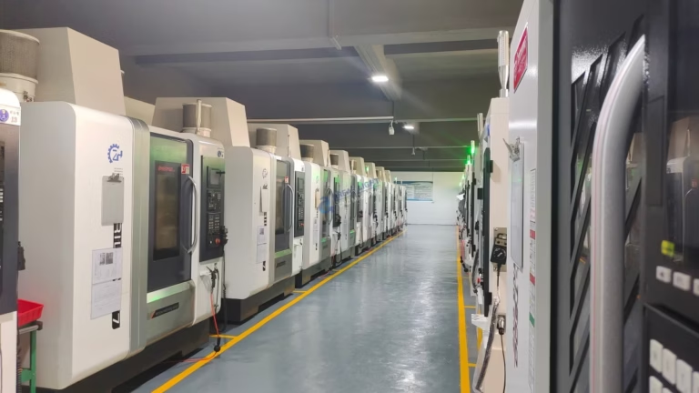
We run 16 simultaneous 5-axis machining centers, plus 12 four-axis mills and 16 mill-turn centers for parts that are mostly rotational.
Which materials are practical on five axes?
Aluminium grades such as 6061, 7075 and 6082 cut fast and hold tolerance well. Stainless 303, 304, 316 and 17-4PH, plus 4140 and 4340 steel, are routine.
Titanium TC4 (Ti-6Al-4V), Inconel and magnesium AZ31B are machined too, but they need slower parameters and more attention to tool wear, so the cycle time reflects that.
How fast can a quote and a first batch move?
Quotation and free DFM analysis come back within 12 hours, and production can start within 24 hours after that. Parts ship in 3–5 days.
There is no minimum order quantity. One prototype and a 10,000-part run go through the same process. Uploads stay confidential, and an NDA is available on request.
Do you finish parts after machining?
Yes. Anodizing, electroless nickel, zinc, silver and gold plating, powder coating, black oxide, bead blasting, polishing and laser marking are handled in-house or through qualified partners.
Laser marking has a minimum character height of 1.5 mm, which matters when you are laying out serial numbers or traceability codes.
Send the model and get a DFM answer before you commit
Upload a STEP file and a drawing. An engineer reviews the 5 axis setup, tolerance stack and fixture access, then replies with a quote and free DFM notes within 12 hours.
12-hour quoteFree DFM analysis100% inspectionNDA on request









