
5 Axis CNC Controllers: The Five Settings That Decide Precision and Cost
Most shops buy the machine and stop there. The gap between a stable ±0.005 mm run and a pile of rework usually sits inside the control. This page covers five controller functions we configure on every 5-axis cell: kinematic compensation, adaptive feedrate, tool center point management, chip and coolant logic, and drift control over long runs. Written for engineers and buyers who need to judge whether a supplier actually uses them.
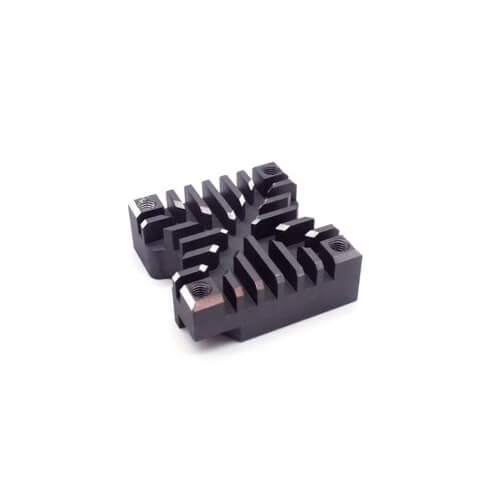
What a 5-axis controller actually controls
The controller sits between your CAM output and the servo amps. Everything below is about what happens in that gap.
Kinematic compensation: mapping the machine before you cut
A 5-axis machine is never geometrically perfect. Squareness between the rotary axes drifts, the spindle grows when it warms up, and the trunnion sags under load. Run a laser interferometer or ballbar test and you get a map of that error field: how far the actual tool tip sits from where the controller thinks it is, across the work envelope.
Feed that map back into the control as a compensation table. The controller then nudges each axis in real time to cancel the measured deviation. This is what shops mean by volumetric compensation. Without it, a perfectly programmed toolpath still produces parts that walk out of position, and the error grows the further you move from the machine origin.
We recalibrate each 5-axis cell on a fixed cycle under our ISO 9001:2015 system. That keeps repeatability stable across batches. When you vet a supplier, ask two questions: do they run volumetric compensation, and how often do they redo it? Skipping this step saves a day of machine time and costs far more in first-article rework.
Adaptive feedrate control based on real cutting load
A CAM post-processor writes one fixed feedrate per toolpath segment. That number is a guess. In a deep pocket or a tight corner the tool suddenly engages far more material, the load spikes, and a fixed feedrate either chatters or snaps the cutter. In light cuts the same number wastes cycle time doing almost nothing.
Adaptive control reads spindle load or servo current and adjusts feedrate while the cut runs. Heavy engagement, slower feed. Light engagement, faster feed. The target is a constant chip load rather than a constant speed along the path.
The payoff shows up in three places. Tool life gets longer because the edge sees a steadier load. Cycle time drops on parts with mixed geometry. And surface finish stays inside Ra 0.8–1.6 μm on walls that would otherwise show chatter marks.
It is not free. Adaptive control needs a stable load signal, and on very small tools the signal is noisy. For thin-wall parts, aggressive feed modulation can deflect the wall and do more harm than a fixed conservative feed. We enable it selectively, not globally.
- 1Good fitPockets and corners where engagement varies sharply along the path.
- 2Good fitLong roughing cycles where tool life drives cost per part.
- 3Poor fitThin-wall sections where feed changes bend the part.
- 4Poor fitMicro tools below roughly Ø1 mm with a noisy load signal.
Tool center point management for true 5-axis motion
On a 3-axis machine the tool tip and the programmed point are the same thing. Add two rotary axes and that stops being true. Rotate the table and the tool tip swings away from the commanded position unless the controller recalculates the kinematics every block.
Tool center point control, usually written TCP or TCPM depending on the control brand, keeps the tip on the programmed path while the rotary axes move. It also lets you change the tool length mid-program without reposting the whole toolpath, because the controller re-solves the offset from the new gauge line.
Where this matters most is in simultaneous work: impeller blades, port features, angled holes drilled in one setup, and blended surfaces that cross a rotary axis. Turn TCP off and the same program will run, but the tip drifts by the tool length times the rotation error. On a 100 mm tool that error is visible immediately.
TCP also changes how you think about fixturing. With the tip held in absolute space, you can position the part near the rotary center for stiffness, or offset it for access, and the post-processor output stays valid.
Which controller function to enable for which part
Use this as a starting point when reviewing a program or auditing a supplier's setup sheet.
| Part feature | Controller function | Why it helps |
|---|---|---|
| Large frame, tight hole pattern | Volumetric compensation | Cancels squareness and thermal drift across the envelope |
| Deep pockets, mixed stock | Adaptive feedrate | Holds chip load steady, protects the cutter |
| Impeller blades, port features | TCP management | Keeps the tip on path through rotary motion |
| Titanium with long chips | Chip and coolant logic | Breaks chips, avoids recutting and heat buildup |
| Long unattended runs | Drift monitoring | Catches growth before parts leave tolerance |
| Thin-wall aluminium | Fixed conservative feed | Adaptive modulation can deflect the wall |
| Micro features below Ø1 mm | Fixed feed, light depth | Load signal too noisy to modulate safely |
Chip and coolant logic written into the control
Chip evacuation is a controller problem, not just a plumbing problem. The control knows where the tool is, how deep it is cutting, and how long the chip has been forming. It can trigger through-spindle coolant at the start of a deep pass, switch to air blast in a dry pocket, and schedule a retract when a chip is likely to be recut.
In aluminium, recutting a chip is the fastest way to a torn surface. In titanium and Inconel, the same chip carries heat back into the cut and shortens tool life. Both problems shrink when the control commands chip-breaking moves and coolant timing on its own logic rather than leaving it to the operator.
The setting that matters most is coolant-on timing relative to tool entry. Coolant that arrives late leaves the first few millimeters of a pass dry. On a deep bore that shows up as a glazed, work-hardened band. We set pre-entry coolant and confirm it during first-article inspection.
Holding accuracy through long runs and thermal drift
A spindle that has run for three hours is not the same size as a cold one. Ballscrews grow, the bed warms unevenly, and the part itself expands as it heats. On a short cycle you never notice. On an eight-hour unattended run, the last parts come off out of tolerance while the first ones passed.
Controllers handle this in two ways. The first is thermal compensation: temperature sensors on the casting and spindle feed a model that offsets the axes as the machine warms. The second is drift monitoring, where the control watches servo following error and position deviation against expected values and flags a trend before it becomes a scrap event.
Both depend on the machine being calibrated regularly. A compensation model built last year no longer matches a machine that has been crashed or had a ballscrew replaced. Under our ISO 9001:2015 system we keep calibration records per cell and inspect 100% of parts before shipment. If a supplier cannot show calibration history, their long-run accuracy claim is a guess.
Questions engineers ask about 5-axis control setup
How do I tell if a supplier actually uses volumetric compensation?
Ask for the calibration method and the recalibration interval, not the machine brand. Shops that do it will name the instrument and the cycle.
A vague answer, or a claim that the machine was accurate from the factory, usually means the step is skipped.
Does adaptive feedrate always reduce cost per part?
No. It reduces cycle time and tool wear on parts with varying engagement, which is where most savings come from.
On thin-wall or micro features it can add risk, so we leave those on fixed feeds.
Can TCP be added to an existing program without reposting?
In most controls TCP is a mode you enable, and the program runs in the machine coordinate frame while the control handles the tip offset.
Tool length changes still need the controller to know the new gauge line, so update the offset table rather than editing the path.
What tolerance can you hold on a 5-axis part?
We work to ±0.005 mm (±0.0002 in) where the geometry and material allow it, with surface finish from Ra 0.2–0.8 μm on fine finishing passes.
Feature access and wall stiffness set the real limit, so we confirm on the DFM review before quoting.
How does thermal drift affect a long unattended run?
The machine changes shape as it warms, so a program that was correct at hour one may not be correct at hour six.
Compensation models plus periodic in-process checks keep the later parts inside tolerance.
Can you work from our CAD files under NDA?
Yes. Uploads are treated as confidential and we can sign an NDA before files are shared.
We return a quotation with free DFM analysis within 12 hours of receiving a complete package.
Send a part and we will tell you what the control has to do
Upload a STEP file and drawing. An engineer reviews the geometry, the tolerance stack and the setup, then returns a quotation with DFM notes within 12 hours.
12-hour quote100% inspectionNo minimum order quantityNDA on request









