
7 Deadly CNC Motion Mistakes Sabotaging Your Machining Precision
Part dimensions drift, bores come out oval, and finishes chatter even when the tool offsets are correct. The seven CNC motion faults below cover backlash, servo tuning, thermal growth, jerk profiles, axis wear, squareness, and interpolation. For engineers and buyers who need to trace a tolerance failure back to the machine rather than the toolpath.
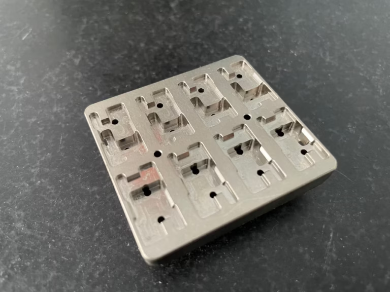
Seven fault paths in the CNC motion chain
Each section gives the failure signature, the parts it ruins, and the check that confirms it.
Backlash and Lost Motion in Feed Drives
Backlash is the lag between a commanded axis move and the slide's actual response. It lives in ball screw and nut interfaces, gearboxes, and coupling wind-up. When the axis reverses direction, the motor turns a little before the table moves. That gap is small but it accumulates over a long toolpath. The damage shows up in contour milling, where every direction change adds another sliver of position error.
A bolt-hole pattern exposes the problem fast. Hole centers land tens of microns off, and the error changes with approach direction. In simultaneous 5-axis work, lost motion on a rotary axis turns into angular deviation, so a flat face on a trunnion machine cuts slightly conical. Operators often blame the post-processor first. The machine is the better suspect when error tracks reversal count.
The check is a ballbar circle test plus laser interferometry across the full stroke. Both separate mechanical lash from servo following error. Once the numbers are known, the controller can pre-load the axis on reversal, but compensation tables only mask wear. On a machine we run, mechanical lash is held below 2 µm, and any screw showing more lash than that gets replaced rather than compensated.
Servo Tuning Parameters That Invite Oscillation
Modern drives use PID loops: proportional, integral, derivative. Set proportional gain too high and the axis hunts around the commanded point. Set it too low and following error grows whenever load changes. Integral windup produces low-frequency hunting. Too little derivative damping lets high-frequency vibration through during sharp cornering. No single gain value is right for both a heavy face mill and a 3 mm end mill.
The audible signature is a growl on direction changes or a faint scallop pattern on straight walls. In bad cases the oscillation excites a structural resonance, and the marks look exactly like tool chatter. That sends teams chasing the wrong cause: they swap holders, shorten gauge length, and change speeds, while the drive gain stays wrong.
Tuning needs a real excitation test, not a guess. A frequency response measurement with an impulse or a swept sine shows the first resonance and the phase margin. From there, notch filters can knock down a known resonance, and feed-forward can cut following error on curved paths. Re-tune after any screw, bearing, or motor swap. The old values rarely transfer.
Thermal Drift: The Invisible Tolerance Thief
Iron and steel grow about 10–12 µm per meter per °C. A 1,000 mm steel screw that warms 5 °C during a long run shifts position roughly 50 µm. That is ten times the tolerance on many of our jobs. The drift is not linear either: it is fastest in the first hour of spindle and axis warm-up, then settles into a slow climb as the shop air temperature changes.
Signs are easy to misread. Parts cut early in the shift hold size; parts cut two hours later drift. Operators compensate by nudging offsets, which hides the trend and breaks repeatability when the next operator takes over. Multi-axis machines add rotary axis growth, so angular position also moves.
Countermeasures are practical. Run a warm-up cycle before the first production part. Keep coolant temperature stable. Hold the shop within a few degrees through the day. And check critical features with a probe or CMM at a repeatable part temperature. If a job runs long, re-measure at the midpoint of the batch, not only at the end.
Jerk-Limited Acceleration and Vibration
Acceleration profiles set how fast an axis changes velocity. A step change in acceleration, called infinite jerk, slams the drive and sends a shock wave through the machine. The axis arrives at position but the structure is still ringing. On a finishing pass, that ringing writes itself into the surface as closely spaced marks.
Jerk-limited profiles ramp acceleration smoothly, so the axis settles faster and leaves a cleaner cut. The trade is cycle time, and this is where engineers argue. A tight corner in a mold core may need a lower jerk limit to hold form accuracy, while a roughing pass can run much higher. Modern controllers expose separate limits for rapid, feed, and corner moves.
Watch for the wrong fix. Damping the whole machine with lower feed rates hides jerk problems but costs throughput. The better route is to set jerk limits per move type, then verify with a ballbar test that dynamic error at corners stays inside the print tolerance.
Motion Faults, Signatures, and Checks
Match the symptom to the test before touching the controller.
| Fault | Typical signature | Confirm with |
|---|---|---|
| Backlash / lost motion | Hole centers shift with approach direction | Ballbar circle test, laser interferometry |
| Servo oscillation | Growl on reversals, scalloped straight walls | Frequency response, step response |
| Thermal drift | Size drifts over the shift | Probe checks, shop temperature log |
| Excess jerk | Closely spaced marks near corners | Ballbar corner test, surface inspection |
| Axis wear | Growing backlash over months | Ballbar trend across service life |
| Squareness error | Out-of-square bores and faces | Squareness and volumetric laser test |
| Interpolation error | 5-axis surface mismatch and blend marks | Test part with known geometry, probe scan |
Wear in Leadscrews, Linear Rails, and Rotary Axes
Wear is not a single event. Ball screw raceways pit, linear rail carriages lose preload, and rotary table bearings develop clearance. Each change adds a little lost motion, and the machine slowly leaves its original accuracy. Most shops notice only when a scrap rate climbs or a customer rejects an assembly.
The pattern of wear is informative. If backlash grows only in a mid-stroke zone, the screw is worn where the machine works most. If it grows at both ends, preload loss or rail wear is more likely. Rotary axes show it as angular error at specific table angles, often where fixtures sit for long runs.
Maintenance beats compensation. Track backlash monthly on a ballbar, and replace screws or re-preload carriages when the trend crosses a set limit. For a rotary axis, check the clamp and the bearing preload together. On our 16 simultaneous 5-axis centers, rotary geometry is re-checked on a schedule rather than after a failure.
Axis Squareness and Volumetric Error
Squareness errors are angular. Two axes that are out of square by 10 arc seconds produce about 5 µm of error over a 100 mm move. On a long part, the error scales up. A gantry or a long bed machine can be off by tens of microns at the far end, even though every single-axis move tests perfect.
Volumetric error is the sum of these angles plus straightness and scale errors across the working volume. It is the reason a part cut in one corner of the table measures differently from the same part cut in another. Single-axis ballbar tests miss it entirely.
The right test is a volumetric laser measurement or a machined test artifact measured on a CMM. Both map error across the envelope instead of one line. Correction is mechanical where possible: level and align the machine, then apply controller compensation for the residual. Re-check after any foundation work, move, or crash.
Controller Interpolation and Kinematic Errors
The controller runs the math that turns a toolpath into axis motion. In 3-axis work, interpolation error shows up as chordal deviation on curved surfaces. Tighter tolerance settings reduce it but load the processor and slow the cut. There is always a balance between surface fidelity and cycle time.
Five-axis work adds kinematic transformation. The controller must convert tool-tip commands into coordinated linear and rotary moves, and any error in the machine model, pivot distances, or tool length propagates into the cut. Symptoms include blend marks where the rotary axes reverse, and surfaces that measure right at the nominal point but wrong nearby.
The fix starts with an accurate kinematic model. Measure pivot points and tool offsets, load them, and verify with a known test part. Then set interpolation tolerance per operation, not once for the whole program. A roughing pass can run coarse; a finishing pass on a sealing face needs the tighter setting.
Motion Error Questions Engineers Ask
How often should backlash be checked on a production machine?
Monthly for machines running two or three shifts, and after any crash or screw replacement. Track the number over time rather than judging a single reading.
A slow trend signals normal wear. A sudden jump points to a loose coupling, a damaged bearing, or a crash that shifted an axis.
Can controller compensation fix a worn ball screw?
It can hide the average error, but it cannot restore lost stiffness or repeatability. Compensation tables are static; wear is not uniform along the stroke.
Use compensation as a short-term measure, then replace the screw when backlash crosses the limit you set for that machine.
Why do parts drift in size over a long run?
Thermal growth is the usual cause. Screws, spindles, and the shop air all warm up during the first hours of a shift.
Run a warm-up cycle, keep coolant and air temperature stable, and re-measure critical features at a repeatable part temperature.
What is the difference between backlash and following error?
Backlash is mechanical lost motion at a direction reversal. Following error is the lag between the commanded position and the axis position while moving.
A ballbar test separates the two. Backlash appears as a step at reversal; following error appears as a size change on the circle.
Does a 5-axis machine need a different squareness check?
Yes. Linear squareness alone is not enough because rotary axes add angular error at the tool tip.
Measure pivot points and tool offsets, then verify with a test part that exercises the rotary axes across their range.
How do you know when jerk limits need to change?
Look at the surface near corners and reversals. Closely spaced marks that repeat with the toolpath geometry point to jerk, not to the tool.
Set separate jerk limits for roughing, finishing, and corner moves, then confirm with a ballbar corner test.
Send a Drawing, Get a Motion-Aware Quote
We review tolerances, geometry, and motion demands before quoting, so the process matches the print. Upload a STEP file and get a quotation with free DFM analysis within 12 hours.
12-hour quote100% inspectionNDA on request









