
7 Essential CNC Cosmetic Finishing Secrets to Master Flawless Surface Quality
This page is for engineers and buyers who own the visible surfaces of a part, not just the tolerance callouts. It walks through the seven decisions that separate an as-machined surface from a cosmetic one, and shows where to draw the line between what the machine can hold and what needs a bench.
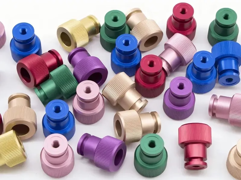
Cosmetic finishing is a sequence, not a final pass
A part can pass every dimensional check and still get rejected under a raking light. The cure is upstream.
Toolpath strategy sets the surface before the last pass
Most engineers treat the finishing pass as the moment surface quality is made. It is not. The texture you see under a light was already decided during roughing, because roughing sets the chip load consistency that the finishing tool inherits. A roughing path that varies chip thickness leaves a wall of uneven stock, and the finisher then cuts a mirror of that variation.
Keep radial and axial engagement steady through the whole path. Constant engagement keeps the load on the insert constant, which keeps the white-noise pattern in the surface constant. If your CAM software offers it, use trochoidal or constant-engagement roughing on cosmetic walls rather than a classic offset path with corners.
Design radii into internal corners. A sharp corner forces the tool to slow, dwell, and change direction while still in contact, and that dwell leaves a witness mark the finisher cannot remove without cutting deeper. A generous fillet lets the machine hold feed rate through the corner and produce a uniform finish.
- 1Stock left for finishing0.2–0.5 mm is enough on aluminium; more stock means more deflection on the last pass.
- 2Corner radiiMatch the radius to at least 1.2 × the cutter diameter where the design allows.
- 3Lead-in and lead-outUse tangential arcs; a plunging entry leaves a dimple on a visible face.
Tool selection and runout decide how bright the surface reads
The cutting edge is what the customer sees. For cosmetic work on aluminium, a polished uncoated carbide cutter or a diamond-coated (PCD) tool usually beats a standard AlTiN-coated tool, because the coating's micro-texture is copied into the surface. On stainless and titanium, the trade-off flips: you want a coating with low friction and good edge retention, and you want it sharp, not honed.
Tool runout matters more than most people expect. A runout of 0.002 mm on a two-flute cutter means one edge takes almost all the cut, so the surface shows a scalloped or banded pattern that varies with the spindle speed. Use precision collets or a hydraulic chuck, and check runout at the tool, not at the holder. If your setup needs a drill chuck, you have already lost the finish on a cosmetic face.
Coolant is the third variable. It is not only about heat. Clean, correctly mixed coolant lubricates the edge and flushes chips that would otherwise be pressed into the surface and dragged along it. Tramp oil, fine fines, and a weak mix show up as cloudy areas and random scratches. On aluminium, a higher concentration and good filtration give a brighter cut. On cast iron, dry or near-dry cutting with air blast keeps the graphite off the surface.
- 1AluminiumUncoated polished carbide or PCD, high positive rake, sharp edge.
- 2Stainless 304/316AlCrN or TiAlN coating, sharp edge, avoid dwelling in the cut.
- 3TitaniumSharp uncoated or AlTiN, low speed, generous coolant flow to the edge.
- 4Coolant checkMeasure concentration weekly; skim tramp oil before it emulsifies.
Deflection control: rigidity and workholding
A cosmetic surface is a low-vibration record. Every source of movement between the spindle and the part is written into the finish, and the last pass is where it becomes visible. Thin walls, tall bosses, and long overhangs move under cutting force, then spring back and leave chatter marks.
Hold the part where it is stiff, and support it where it is not. For thin-walled parts, support with a soft jaw, a low-melt fixture, or vacuum. For tall features, step down in small axial increments instead of taking one deep pass. A finishing pass with a light radial stepover and a short flute length is usually more stable than a long tool reaching deep.
Keep the tool as short as the geometry allows. A tool that overhangs 4 × diameter is 16 times more flexible than one that overhangs 1 × diameter. If the reach forces a long tool, reduce the radial engagement and increase spindle speed slightly to keep the chip load in a range that cuts rather than rubs.
- 1Thin wallsRough both sides before finishing either; alternate passes to balance stress.
- 2WorkholdingSupport under the visible face; a flexing floor shows as a wavy reflection.
- 3Tool overhangAim for 3 × diameter or less on the finishing tool whenever possible.
Sequencing machine work and bench work on cosmetic parts
Cosmetic parts rarely come off the machine ready to ship. They come off the machine ready for the bench, and the order of operations on that bench decides whether the finish survives. The rule is simple: do all cutting before all polishing, and all polishing before all coating. Polishing a part after anodizing or plating removes the coating and leaves an uneven edge.
Deburr before you polish. A burr that is polished while attached becomes a smear, and when it breaks off it leaves a pit. Use a controlled deburring tool or a fine stone on edges, then move to the polishing step. On aluminium, a light bead blast produces a uniform matte that hides small tool marks and gives anodizing a consistent base. On stainless, brushing gives a directional grain that is easier to keep consistent than a mirror polish.
Handle parts between steps. Gloves, foam nesting, and separate trays for polished parts prevent the fingerprints and fine scratches that fail a cosmetic inspection. If a part is inspected under a raking light, inspect it under the same light throughout the process so the standard does not drift.
- 1Order of operationsMachine, deburr, polish or blast, clean, then coat or anodize.
- 2Directional grainKeep brushing lines parallel on adjacent faces; crossed grain looks like a defect.
- 3Blast mediaFine glass bead gives a softer matte than angular media on aluminium.
Typical cosmetic finishing routes by material
Starting points for quoting; the final route depends on the drawing and the inspection light.
| Material | Machined finish | Bench step | Final look |
|---|---|---|---|
| 6061-T6 aluminium | Ra 0.8–1.6 μm | Fine bead blast | Matte, anodize-ready |
| 7075 aluminium | Ra 0.8–1.6 μm | Polish, then blast | Even satin, hides marks |
| 304 / 316 stainless | Ra 0.8–1.6 μm | Directional brush | Brushed grain |
| 17-4PH stainless | Ra 0.2–0.8 μm | Polish, passivate | Bright, clean |
| Ti-6Al-4V | Ra 0.8–1.6 μm | Light blast | Uniform matte |
| Brass C36000 | Ra 0.2–0.8 μm | Polish | Bright, then plate |
Cleaning and passivation before the part is packed
Residue is the quiet cause of a rejected cosmetic part. Coolant film, polishing compound, and handling oils sit in the surface and show up as cloudy patches after anodizing or plating. Clean the part after the last bench step, using a sequence that matches the material: alkaline cleaner for aluminium, a passivation step for stainless, and a deionized water rinse before drying.
Passivation on stainless is not a polish. It removes free iron left by cutting tools and restores the passive oxide layer, which improves corrosion resistance and gives a more uniform appearance. Citric passivation is common and easier to control than nitric in a job-shop setting. Inspect after passivation under the same raking light used for the cosmetic check.
Pack the part the way you want it to arrive. A polished face touching a cardboard box will pick up scratches in transit. Use foam, tissue, or a molded tray, and keep parts from touching each other. If the customer inspects on receipt, the last 10 minutes of packing decide the first impression.
- 1Rinse waterDeionized or RO water avoids mineral spots after drying.
- 2GlovesNitrile gloves on polished and blasted parts; bare hands leave acid marks.
- 3DryingFiltered air or a clean oven; shop air can carry oil mist.
Questions engineers ask about cosmetic finishing
What surface finish can be held directly off the machine?
On aluminium and brass with a fresh sharp cutter and a stable setup, Ra 0.2–0.8 μm is achievable on flat and gently curved faces.
On stainless and titanium, Ra 0.8–1.6 μm is a more realistic as-machined target without a bench step. Deep pockets, long reach tools, and thin walls push the number higher.
Can cosmetic finishing be quoted from a STEP file alone?
A STEP file tells us the geometry, which is a large part of the cost. It does not tell us which faces are visible, what inspection light will be used, or whether a bench step is allowed.
Mark the cosmetic faces on the drawing or in a screenshot. That single note usually changes the process plan and the price.
Does anodizing hide machining marks?
It amplifies them. Anodizing is a conversion coating that grows from the surface, so scratches, chatter, and uneven blast texture remain visible and can become more obvious.
Fix the surface before anodizing. A uniform fine bead blast is the most reliable base for a consistent anodized look.
How do we avoid witness marks at tool entry and exit?
Use tangential arc lead-in and lead-out, keep the entry off the cosmetic face if the geometry allows, and avoid dwelling at the end of a pass.
If a mark is unavoidable, plan the path so it lands on a non-cosmetic edge or a face that will be blasted.
What causes a cloudy finish after polishing?
Usually residue or heat. Polishing compound left in the surface, or too much pressure that burns the material, both read as cloudiness under a light.
Clean with the correct chemistry for the alloy and keep the polishing pressure low with a fresh wheel.
Can you handle both the machining and the finishing?
Yes. We machine, deburr, blast or polish, clean, and arrange anodizing, plating, powder coating, and laser marking so the sequence stays under one process control.
Every part is inspected before shipment, and inspection reports are available on request.
Send the drawing and the cosmetic callouts
We will review the visible faces, the material, and the target finish, then come back with a process plan and a quote.
12-hour quote and DFM100% inspectionNDA on request









