
7 Essential DIY CNC Mill Tips to Avoid Costly Mistakes and Save Thousands
Most scrapped hobby parts fail for the same handful of reasons: loose workholding, wrong speeds, poor chip clearing, no measurement plan. This guide is written for engineers and shop owners running a benchtop or small-frame mill. Read it and you will know which symptom points to which cause, and what to change before the next cut.
In this article
- 1
- 2
- 3
- 4
- 5
- 6
Symptom, likely cause, and what to do first
Use this table before you change any program settings. Match the symptom you actually see.
| Symptom | Likely cause | First move |
|---|---|---|
| High-pitched squeal, visible ripple marks | Tool stickout too long; workholding not rigid | Shorten gauge length; re-clamp and re-check runout |
| Tool snaps on the first pass | Feed per tooth too high for the flute count | Cut feed 30–50%; verify flute count in CAM |
| Part moves in the vise mid-cut | Clamp force below cutting force; parallels not seated | Seat the part on parallels; torque bolts evenly |
| Bore comes out oval or tapered | Spindle or head tram out of alignment | Tram the head; check spindle runout under 0.01 mm |
| Thin walls bow after unclamping | Residual stress in the blank; heavy roughing pass | Take lighter finishing passes; stress-relieve the stock |
| Chips weld to the cutter edge | No coolant or air blast at the cut zone | Add flood coolant or a directed air blast |
| Surface finish worse than Ra 3.2 μm | Dull tool; stepover too wide on the finish pass | Change the insert; drop stepover to 5–10% of Ø |
| Dimensions drift over a long run | Thermal growth in spindle and ballscrews | Warm up 10–15 min; re-zero between batches |
DIY CNC mill tips that cover the mistakes you actually make
A benchtop mill does not fail because the operator is careless. It fails because a small machine has a narrow window between cutting well and cutting badly. The frame is lighter, the spindle has less torque, and the toolholder runout is often three to five times what a production VMC holds. Those DIY CNC mill tips below are ordered by how much money each mistake usually costs.
Start by matching what you see to what caused it. Chatter, snapped end mills, and out-of-tolerance bores rarely come from the same root cause, and fixing the wrong one wastes both stock and time. The symptom table above is the fastest way in. The sections that follow explain why each fix works and when you should stop adjusting and move the job to a machine that can hold the tolerance.
One rule applies to all seven: change one variable at a time and record the result. Hobby mills respond well to systematic tuning and badly to guesswork. Log spindle speed, feed, depth of cut, and the finish you got. After a dozen parts you will have a baseline that beats any generic speed-and-feed chart.
- 1Rigidity firstA short, thick tool in a solid vise outperforms a long tool in a perfect program.
- 2Record everythingSpeeds, feeds, depths, and results. Your own log beats any chart.
- 3Know the limitIf the part needs ±0.005 mm, a light benchtop frame is the wrong machine.
Material choice and workholding set the ceiling on accuracy
Aluminum 6061 is forgiving. It cuts clean at 300–600 m/min surface speed with a two- or three-flute carbide end mill, and it tolerates a slightly loose setup without punishing you. Stainless 304 and titanium Ti-6Al-4V are a different job. They work-harden, they push cutting force back into the frame, and they need slower surface speeds, rigid setups, and sharp tooling. Buying cheap 7075 with unknown temper is a common trap: improperly aged stock machines like a different alloy and moves after clamping.
Check the material certificate before you cut. Hardness matters more than the alloy name on the box. A 6061-T6 blank at 95 HB behaves nothing like soft 6061-O, and the feeds that worked on one will break tools on the other.
Workholding is where most hobby setups lose. A part held in a worn vise with loose parallels will shift under a 6 mm depth of cut. Clamp force should be two to three times the expected cutting force, applied evenly. Over-tightening distorts thin walls and spring back after unclamping; under-tightening lets the part creep. Use a torque wrench on fixture bolts and check the part with a dial indicator before every run.
For 5-axis or multi-face work, a tombstone or a machined soft jaw holds better than improvised clamps. Soft jaws cut to the part profile give full contact along the wall, which spreads the load and cuts vibration at the source.
Toolpath, feeds, and chip evacuation control tool life
Chatter comes from a combination of tool stickout, radial engagement, and spindle speed. Shorten the gauge length to the minimum the geometry allows. Then reduce radial engagement, not just feed. A 12 mm end mill taking a 6 mm radial cut on a light frame will sing; the same tool at 1.2 mm radial engagement with a deeper axial cut runs quiet and removes metal faster.
Feeds and speeds are not a formula to memorize. Start from the manufacturer surface speed for the material, then adjust for your machine rigidity. For 6061 aluminum, 300–600 m/min is a reasonable starting band; for 304 stainless, 60–120 m/min. Feed per tooth on a 6 mm three-flute cutter in aluminum sits around 0.05–0.10 mm. If the chips come out as dust, you are rubbing. If the tool snaps, you are overloading it.
Chip evacuation is the most ignored item on this list. Recut chips weld to the cutting edge, raise the temperature, and dull the tool in minutes. On aluminum, a directed air blast often works better than flood coolant because it clears the pocket without thermal shock. On steel and stainless, flood coolant keeps the edge cool and flushes chips out of deep pockets. Never run a deep pocket dry on a benchtop mill.
Listen to the cut. A steady hum with short, curled chips means the setup is working. A high-pitched squeal or a thumping sound means something is loose, too long, or spinning too fast.
- 1Aluminum300–600 m/min, air blast or mist, watch for built-up edge.
- 2Stainless 30460–120 m/min, flood coolant, never dwell in the cut.
- 3Titanium Ti-6Al-4V40–80 m/min, high-pressure coolant, sharp edges only.
Measurement and post-processing decide whether the part ships
Measure twice, but with instruments that match the tolerance. A caliper is fine for a rough check, but it will not prove a ±0.05 mm bore. Use a micrometer for outside diameters, a bore gauge or pin gauges for holes, and a dial test indicator for face runout. Let the part cool before the final measurement. Aluminum grows about 23 μm per meter per degree Celsius, so a warm part measures larger than it will at room temperature.
Set a zero reference on the machine and check it against the part. If the vise moved or a tool pulled out, the error shows up in the first feature, not the last. Re-zero between batches on long runs.
Post-processing is not cosmetic. A sharp burr on a mating face can hold two parts apart by 0.1 mm, which ruins a fit that was correct off the machine. Deburr before you measure the final dimension, not after. Bead blasting removes tool marks and hides small scratches, but it also rounds edges, so mask any face that needs a crisp corner. Anodizing adds roughly 5–25 μm per surface depending on the process, so plan the pre-anodize dimension accordingly.
If the part needs a fine finish, the last pass should be light. A 0.2 mm finishing pass at 5–10% stepover leaves a surface in the Ra 0.8–1.6 μm range on aluminum. Trying to finish with a heavy pass just transfers the roughing marks to the final surface.
Step by step: tune a benchtop mill for a stable cut
Work through these steps before you blame the program or the tool.
- 1Tram the head and check spindle runoutIndicate the table in X and Y. Aim for under 0.02 mm over 150 mm, and spindle runout under 0.01 mm. Re-tram after moving the machine.
- 2Reduce tool stickoutSet gauge length to the shortest value the geometry allows. Every extra 10 mm of stickout costs rigidity fast. Use a stub holder for small cutters.
- 3Seat the part and verify clamp forceClean the vise jaw faces and parallels. Tap the part down, then torque bolts evenly to two to three times the expected cutting force.
- 4Set a conservative starting pointUse the material surface speed band, half the recommended feed per tooth, and 50% of the axial depth you think you can take. Then increase one value per test cut.
- 5Fix chip evacuation before the first deep pocketAir blast for aluminum, flood coolant for steel and stainless. Aim the nozzle at the cut zone, not the whole table.
- 6Measure a test feature, then adjustCut one pocket or boss, measure it cool, and compare to nominal. Correct cutter compensation before running the rest of the part.
- 7Log the result and repeatWrite down speed, feed, depth, tool, and finish. The next job starts from data, not from scratch.
Common questions about DIY CNC mill tips
Why does my end mill break on the first pass?
The usual cause is feed per tooth that is too high for the flute count, or a cutter that is not seated fully in the holder. Check the number of flutes in your CAM tool library against the physical tool. A three-flute cutter programmed as a two-flute tool gets 50% more chip load per tooth than intended.
Second cause is runout. Indicate the cutter near the flutes. If it reads over 0.02 mm, clean the holder taper and reseat the collet.
How do I stop chatter without slowing the whole job down?
Reduce radial engagement first, then shorten tool stickout, then adjust spindle speed. Radial engagement has the largest effect on a light machine. Dropping from 50% to 10% radial width often removes chatter completely while keeping the metal removal rate reasonable.
If chatter persists at low engagement, the frame or the workholding is the limit. Add support under the part and re-check.
Do I need flood coolant on a benchtop mill?
For aluminum, a directed air blast or mist is often enough and keeps the shop cleaner. For steel, stainless, and titanium, yes. Flood coolant carries heat away and flushes chips from deep pockets where recutting would ruin the edge.
If you cannot run flood, use a mist system and take lighter axial depths so chips clear on their own.
How much material should I leave for a finishing pass?
Leave 0.2–0.5 mm on walls and floors for the finish pass. On a benchtop machine, use a 5–10% stepover relative to cutter diameter for the last pass. That keeps radial force low and produces a finish in the Ra 0.8–1.6 μm range on aluminum.
Leaving less than 0.1 mm risks rubbing instead of cutting, which dulls the tool and worsens the finish.
Why does my part measure correct on the machine but wrong after unclamping?
Clamping force is distorting the part. Thin walls and unsupported floors spring back once the vise opens. Support the part underneath, reduce clamp force, and take lighter finishing passes.
Residual stress in the blank is the other cause. Stress-relieved or pre-machined stock moves far less after the final cut.
When should I send the job to a machine shop instead?
Send it out when the tolerance is tighter than your machine can hold, when the material is difficult to cut on a light frame, or when the geometry needs five axes. A shop running simultaneous 5-axis centers can hold ±0.005 mm and reach features a benchtop mill cannot index to.
Prototyping a difficult part externally also gives you a reference dimension to compare against when you bring the job back in house.
Send the parts your benchtop mill cannot hold
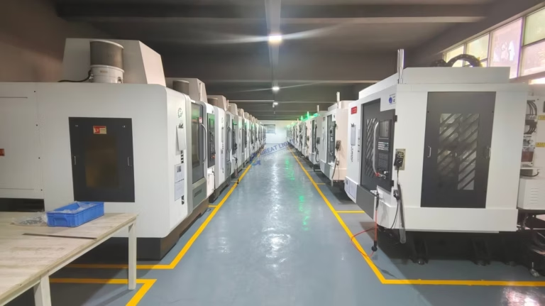
We quote from your CAD files and give a free DFM review within 12 hours. Tolerances to ±0.005 mm, 127 CNC machines, no minimum order quantity.
12-hour quote100% inspectionNDA on request
More machining notes
We publish setup notes, tooling trials and inspection data from the factory floor.











