
Quaser MV 154 That Changes How You Plan a Job
A working guide for process engineers and shop leads who already run or quote on the MV 154. Seven habits that decide whether the machine pays for itself: fixturing for one setup, dynamic milling parameters, in-process probing, tool life rules, and CAM choices that match the machine. Read it to judge which of these fit your parts and which do not.
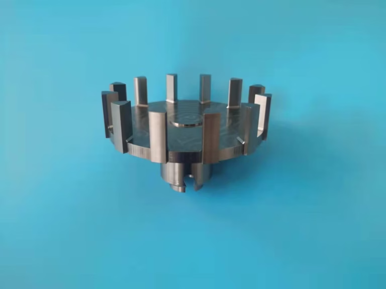
Start with one setup, not with spindle speed
The biggest gain on a Quaser MV 154 does not come from pushing the spindle. It comes from removing the second and third setup. A five-axis trunnion table lets the head reach the top, both sides, and the front of a part without re-clamping, but only if the fixture is designed for it from the start.
Fixture design drives this. Aim for access to five sides: clamp on a low boss, a thin web, or a sacrificial pad the operator can cut away at the end. Hydraulic vises and modular tombstones work well on housings and brackets. Thin-wall parts need soft jaws or a vacuum plate instead, or the clamp pressure will move the wall during the finish pass.
Single setup is not always right. A simple plate with one critical bore is faster on a three-axis machine with a vise. Run the numbers before moving work to the five-axis table: if the part has tight true position between features on different faces, one setup wins. If it is flat and open, it does not.
- 1Good candidatesHousings, manifolds, brackets with features on four or five faces
- 2Bad candidatesFlat plates, single-face pockets, parts under 50 mm with loose tolerance
- 3Fixture ruleLeave the finish pass on the clamp side for last
- 4CheckConfirm the trunnion swing clears the fixture at every A and C angle
Dynamic milling: shallow radial, deep axial
The MV 154 sits on a bridge-type casting with polymer concrete fill. That mass absorbs vibration, which is why you can take a deeper axial cut than a lighter machine of the same envelope. Traditional slotting buries the full width of the cutter and loads one flute at a time. Dynamic milling does the opposite: keep radial engagement at 8–12% of tool diameter and push axial depth to 2–3 times the diameter. Chip load stays constant, cutting force stays predictable, and heat leaves with the chip instead of soaking into the part.
This suits aluminum and mild steel with a solid carbide end mill on a 12,000–15,000 rpm spindle. It suits deep pockets and long side walls, where a conventional path would need multiple step-downs and chatter control. It does not suit every job. Small tools under 6 mm, thin ribs, and long reach holders will deflect before the strategy pays off. Hardened tool steel above 45 HRC also prefers a more conservative radial load.
Coolant matters here. Through-spindle high-pressure coolant clears chips from a deep axial cut that flood coolant would never reach. On aluminum, air blast plus a light mist often works better than flood, because it keeps the chip from re-cutting and avoids thermal shock on a finished wall.
- 1Radial engagement8–12% of cutter diameter, held constant
- 2Axial depth2–3 × diameter for aluminum and mild steel
- 3When to stopTool under 6 mm, thin ribs, or reach over 4 × diameter
- 4Chip removalThrough-spindle coolant or air blast on deep pockets
Roughing approach by part type
Starting points for a 12,000–15,000 rpm spindle. Adjust to the tool and the holder you actually own.
| Part type | Strategy | Radial engagement | Watch for |
|---|---|---|---|
| Aluminum housing, deep pocket | Dynamic milling | 8–10% of Ø | Chip packing; use high-pressure coolant |
| 6061 bracket, open profile | Dynamic milling | 10–12% of Ø | Thin floor lifting under axial load |
| 4140 plate, 30 HRC | Conventional step-down | 40–50% of Ø | Tool wear on the corner radius |
| Thin-wall tube, 2 mm wall | Light radial, high speed | 5–8% of Ø | Deflection; support from inside |
| Titanium TC4 pocket | Constant chip load, low speed | 6–8% of Ø | Heat at the cutting edge; coolant aimed at the tip |
Probing and tool life: make the machine check itself
A finishing pass on a part worth thousands of dollars is the wrong place to discover a broken tool. Spindle probes and tool setters turn that risk into a routine. Measure the tool after the roughing cycle, compare against the offset in the control, and let the program decide whether to continue. Tool breakage detection on a 120-tool changer is cheap insurance on long unattended runs.
In-process probing goes further. Touch the datum, set the work offset, and measure a critical feature before the finish pass. If the stock allowance is off by 0.3 mm, the program can shift the path instead of scrapping the part. This is where ±0.005 mm capability becomes repeatable instead of lucky. Check the probe stylus and calibration ball on a schedule. A drifting probe is worse than no probe, because people trust it.
Set tool life limits in the control by time or by number of parts, not by operator feel. Log when each tool is changed and why. After a few weeks the log shows which tools actually fail early and which limits are too conservative. That data beats guesswork every time.
- 1Probe scheduleCalibrate stylus and ball weekly, log the result
- 2Offset checkMeasure tool after roughing, before finishing
- 3Tool life ruleSet by part count, review monthly against the log
Match CAM output to the machine's kinematics
Post-processor quality decides whether a five-axis toolpath runs smoothly or stutters. A generic post will produce points the control cannot blend, and the machine will slow at every block. A post tuned to the MV 154 keeps the rotary axes moving together, applies the right feed rate at the tool tip, and respects the trunnion limits. Ask for a test cut on a known part before accepting a new post.
Watch tool axis control on deep cavities. A lead angle of 10–15° off the surface normal puts the cutting edge in a better position and lets you use a shorter, stiffer tool. Full 90° engagement on a ball nose is slow and wears the tip. For finishing molds and housings, this single change often cuts cycle time without touching the spindle speed.
Simulation is not optional. Verify the whole program in the CAM software, including fixture and holder models, then run a dry cycle on the machine with the feed override down. Collisions on a five-axis machine are expensive and slow to recover from.
- 1Post processorMachine-specific, tested on a known part
- 2Lead angle10–15° off normal for deep cavity finishing
- 3VerificationFull simulation plus dry run before first cut
Small habits that hold the gains
Efficiency on a five-axis machine decays unless someone owns the process. Keep a setup sheet with fixture photos, probe positions, and tool numbers for every recurring part. The next run takes minutes to set up instead of hours. Record the actual cycle time and compare it against the quoted time. A gap of more than 15% means the process, not the operator, needs attention.
Track scrap by cause, not just by percentage. If most scrap comes from one feature on one part, the fix is a process change, not a reminder to be careful. Review the tool life log and the probe log together at the same weekly meeting. The pattern usually shows up in two or three weeks.
None of this needs new software. A shared spreadsheet and a fixture photo folder will do. The point is to stop solving the same problem twice.
- 1Setup sheetFixture photos, probe positions, tool numbers per part
- 2Cycle timeCompare actual against quoted every run
- 3Scrap reviewGroup by cause and by feature, review weekly
Questions engineers ask before quoting
What part size can the Quaser MV 154 handle?
The MV 154 is a compact five-axis platform. In our shop the five-axis centers cover travel envelopes from 500 × 500 × 450 mm up to 4,000 × 400 × 150 mm depending on the model, with a Ø400 mm rotary table on the trunnion machines.
For parts that do not fit, we move the job to a larger three-axis or mill-turn center and split the operations. Send the 3D model and we will tell you which machine the part should run on.
How do you decide between one setup on the five-axis and two setups on a three-axis?
Look at the tolerance between features on different faces. If true position matters across faces, one setup removes the stack-up error from re-clamping. If the part is flat with a single critical face, a vise on a three-axis machine is usually faster and cheaper.
The deciding numbers are the tolerance stack, the number of faces with features, and the fixture cost. We run that comparison during DFM review, before quoting.
What tolerance and surface finish can you hold?
Our standard machining tolerance is ±0.005 mm (±0.0002 in). Surface finish ranges from Ra 0.2–0.8 μm on fine finishes to Ra 1.6–3.2 μm as machined, depending on the material and the operation.
Tolerance on a specific feature depends on the geometry, the material, and whether the feature is cut in the same setup. We confirm what is achievable per feature during the DFM review.
Which materials run well on this machine?
Aluminum grades 6061, 6061-T6, 7075, 2024, and 6082 are the most common. Stainless 303, 304, 316L, and 17-4PH run well with the right coolant and feed. We also machine 4140 and 4340 steel, titanium TC4, Inconel, copper, brass, and engineering plastics including POM, PEEK, and PC.
Material choice changes the cutting strategy more than the machine. Tell us the grade, not just the family, and we will set the parameters accordingly.
Can you work from our 3D model and keep it confidential?
Yes. Upload the STEP or native file and we return a quotation and a free DFM analysis within 12 hours. Production can start within 24 hours after the order is confirmed.
All uploads are treated as confidential. An NDA is available on request before you send any files.
What is the minimum order quantity?
There is no minimum order quantity. We run from one prototype to 10,000+ part runs on the same process.
For a single prototype we still write a setup sheet, so the second and third units run on the same fixture and the same probing routine.
Send the model, get a process plan with the quote
Upload your 3D file and we will return a quotation, a free DFM analysis, and a note on which machine and fixture the part should run on. Quotation within 12 hours.
12-hour quote100% inspectionNDA on requestNo minimum order









