
Advanced ODM Metal 3D Printing Solutions for 2026
This page explains how advanced ODM metal 3D printing is actually run in 2026: which geometries belong on a laser powder bed machine, which do not, and how the printed blank gets machined, heat treated and inspected before it ships. Written for design engineers and sourcing engineers who have to approve a process, not a brochure.
What changed, and what still needs a machinist
Metal printing stopped being a prototyping-only tool. The finishing chain is what decides whether a part is usable.
Where laser powder bed printing earns its place
Two processes carry almost all production work today: direct metal laser sintering (DMLS) and selective laser melting (SLM). Both spread a layer of metal powder, fuse the cross-section with a laser, and drop the build plate by one layer height. Layer heights run 20–60 μm depending on the alloy and the detail you need. A 30 μm layer on a 60 mm tall part means roughly 2,000 passes, which is why build orientation drives both cost and surface finish.
The case for printing is geometry, not speed. Internal channels that a cutter cannot reach, conformal cooling paths that follow a curved surface, lattice regions that remove mass without losing stiffness, and assemblies consolidated from six machined parts into one printed body. Those are the parts where advanced ODM metal 3d work pays for itself. If your part is a turned shaft with two diameters and a thread, print it and you will spend more on finishing than on a bar of 17-4PH.
Aluminium and stainless dominate. AlSi10Mg and 6061-class powders cover housings and brackets; 316L and 17-4PH cover corrosion and strength demands; Ti-6Al-4V covers medical and aerospace where the material cost is justified. Inconel grades show up in hot sections. Material choice should be settled before the build, because switching alloy means switching laser parameters and often a new support strategy.
- 1Good fitInternal channels, lattice, consolidation, low-volume complex geometry
- 2Poor fitSimple prismatic parts, tight flatness on large faces, high-volume simple shapes
- 3Decide earlyAlloy, build orientation and support layout before the first build
Design rules that survive contact with the machine
Minimum wall thickness sits around 0.4 mm for most alloys, but that is a lower bound, not a target. Walls under 1 mm distort more easily during cooling and are hard to support. Keep load-bearing walls at 1.5–3 mm and use ribs or lattice where you need stiffness instead of thickness.
Overhangs below 45° from horizontal need support. Support is not free: it consumes laser time, it must be cut or ground off, and the surfaces it touched usually need machining or bead blasting. A part designed with self-supporting angles can cut build time by a third. This is the single largest lever a designer has.
Holes print undersize. A Ø8 mm hole typically comes out 0.1–0.3 mm small depending on orientation and alloy, so any hole with a tolerance tighter than ±0.1 mm should be printed undersize and drilled or bored afterward. Threads should be printed as pilot holes and cut with a tap. Blind holes trap powder, so add an escape path or accept a cleaning step.
Shrinkage compensation is handled in the build file by scaling the model per alloy, usually 0.2–0.5 percent. It is not exact, which is the practical reason tight tolerances are held on the machined features, not the as-built surface.
As-built versus machined: what to expect
Values below describe what we hold on the machined features of a printed part, not on raw as-built surfaces.
| Feature | As-built condition | After machining / finishing |
|---|---|---|
| General tolerance | ±0.1 mm on small parts | ±0.005 mm on machined faces |
| Surface finish | Ra 8–12 μm typical | Ra 0.8–1.6 μm; Ra 0.2–0.8 μm on request |
| Hole diameter | 0.1–0.3 mm undersize | Bored to nominal, H7 available |
| Flatness on large faces | Distortion risk after cooling | Face milled, then verified |
| Threads | Pilot hole only | Cut by tap or thread mill |
| Internal channels | Rough walls, powder residue | Flushed; polished where reachable |
The finishing chain: support removal, HIP, heat treat, CNC
Support removal comes first. On a well-supported build, the plate is cut off by wire EDM or band saw, then supports are removed by hand tools, a CNC path, or both. What matters to the print buyer is the witness marks. Any surface that had support will show it, so either move supports to non-critical faces or plan a machining allowance of 0.3–0.5 mm on those faces.
Stress relief follows. The rapid heating and cooling of laser melting leaves residual stress that makes a part move when supports are cut. A stress-relief cycle before removal from the plate is standard for thin walls and long, slender geometry. Where fatigue life or internal density matters, hot isostatic pressing (HIP) closes internal porosity; it adds cost and a day or two, so it belongs on parts that actually see cyclic load.
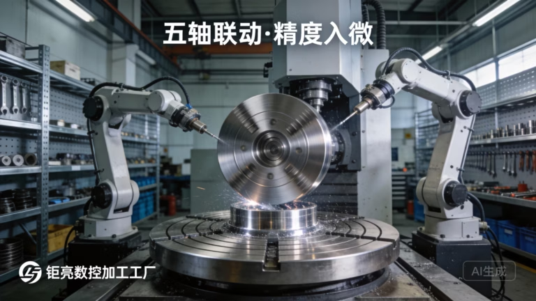
Then the part gets machined. On our side that means 5-axis work for datums, sealing faces, bearing bores and thread features, on 16 simultaneous 5-axis centers among 127 high-precision CNC machines. A printed near-net blank plus a 5-axis finishing pass often beats both pure printing and pure machining on cost when the geometry is complex but the critical features are conventional.
Surface finishing closes it out. Bead blasting knocks down as-built roughness and removes loose powder. Anodizing, electroless nickel, powder coating or laser marking are applied after machining, so make sure the drawing says which surfaces are cosmetic and which are functional. Laser marking holds a minimum character height of 1.5 mm.
- 1Allowance0.3–0.5 mm on supported and critical faces
- 2HIPFor cyclic load and pressure tightness, not for every part
- 3DatumsMachine the datum faces first, then locate everything from them
How to judge an ODM partner before you send the PO
Ask what happens after the build. A printer without machining capacity ships you a blank and a problem. A partner that prints, heat treats, machines, finishes and inspects under one roof removes the handoff where tolerances and schedules usually get lost. That is the whole argument for an integrated ODM rather than a print shop plus a machine shop.
Certifications matter, but they matter as a floor. ISO 9001:2015 covers general quality systems; IATF 16949:2016 is the automotive requirement; ISO 13485:2016 covers medical devices; ISO 27001:2022 covers how your files and drawings are handled. What you should test is whether the paperwork matches the floor: incoming powder certificates, in-process measurements, and a final inspection report you can actually read.
Our position: 15 years in business since 2011, 3 wholly-owned plants, 7,600 m² of floor space, 150 technicians, and a Singapore factory at No.3 Joo Koon Circle alongside the Dongguan operation. We run no minimum order quantity, from one prototype to 10,000+ part runs, with quotation and free DFM analysis within 12 hours and production able to start within 24 hours of release.
The practical test before awarding work is a single part with a machined critical feature. Send the drawing, ask for the build orientation and support plan, and check whether the quotation separates print time from finishing time. A quote that lumps them together tells you the finishing step has not been thought through.
Print, machine, or both
A rough guide for the first conversation on any new part.
| Part characteristic | Recommended route | Why |
|---|---|---|
| Internal channels, curved cooling | Print + CNC finish | No cutter reaches the channel |
| Six parts bolted together | Print as one body | Removes joints, fasteners and assembly time |
| Simple shaft or bracket | CNC from bar stock | Cheaper, faster, tighter all over |
| Large thin-walled housing | Print + stress relief + CNC | Distortion control before finishing |
| Tight bore and seal face | Print near-net + 5-axis | As-built cannot hold the tolerance |
| Low volume, complex, high mix | Print + finishing | Tooling cost is avoided |
Alloy selection for printed parts
Aluminium powders such as AlSi10Mg print well and machine easily, which makes them the default for housings and brackets. Where you need 6061 or 7075 properties in the final part, print the near-net geometry and machine the functional surfaces, because those alloys behave differently in the powder bed than in bar form.
Stainless and tool steels hold up better under load. 316L and 17-4PH (SUS630) are the common choices for corrosion and strength; 420 and 440C come in for wear surfaces that get ground after printing. Titanium grades TA1, TA2 and TC4 (Ti-6Al-4V) are used where weight and biocompatibility drive the decision, and they are also the grades that demand the most care in support removal and finishing.
For hot or corrosive service, Inconel is the usual answer, with the tradeoff that it is slow to print and hard to machine. Copper alloys such as C110 and beryllium copper print with high thermal conductivity, useful for heat-exchange geometry that cannot be made by drilling. Bring the service conditions, not just the alloy name, and the material decision usually becomes obvious.
Questions engineers ask before the first build
Can a printed part hold ±0.005 mm?
Not as-built. The printed surface typically sits within ±0.1 mm on small parts. The ±0.005 mm figure applies to features we machine afterward, such as bores, sealing faces and datums. Design the drawing so critical tolerances land on machined surfaces.
Do I always need HIP?
No. HIP closes internal porosity and improves fatigue life, but it costs money and adds lead time. Use it for parts under cyclic load, pressure-tight components, or where internal density is specified. For brackets and housings, stress relief is usually enough.
How much machining allowance should I add?
0.3–0.5 mm on any face that carries support or a critical tolerance. Add the allowance in the model before the build, not in a note. It keeps the build file and the finishing plan consistent.
What is the smallest feature you can print?
Walls down to roughly 0.4 mm in most alloys, though 1.5–3 mm is a safer range for load-bearing walls. Overhangs below 45° from horizontal need support, and support removal leaves marks on the surfaces it touched.
Can you print and machine in one order?
Yes. Printing, heat treatment, 5-axis machining, finishing and inspection run under one roof across our three plants. Quotation and free DFM analysis come back within 12 hours, there is no minimum order quantity, and production can start within 24 hours of release.
How are internal channels cleaned?
Channels are flushed to remove trapped powder, and polished where a tool can reach. Very long or tortuous channels may need an escape path designed in. Tell us the channel length and diameter and we will confirm what is achievable before the build.
Send the part, get a build and finishing plan
Upload your STEP file and drawing. We will return a quotation, a free DFM analysis and a build orientation proposal within 12 hours.
12-hour quoteNo MOQIATF 16949 / ISO 13485Uploads kept confidential









