
AMR composite robot: the transformative power of the CNC treatment industry
A working guide for engineers weighing mobile robot arms against fixed CNC cells. It covers what the arm can actually hold, how the additive and subtractive steps split, and where the tolerance still has to come from a machine bed.
What this page covers
Where an AMR composite robot fits in a machining workflow, and where it does not.
What an AMR composite robot actually is
An AMR composite robot is a mobile base carrying a robot arm that can both add material and cut it. The additive head lays down polymer, composite, or metal-deposition beads. The subtractive head follows with a spindle to face, drill, tap, or trim the same geometry. The point is to skip the fixture change between printing a near-net blank and finishing it.
The mobile base matters less than people expect. Moving a robot to a large frame is useful for aerospace ribs, boat hulls, and wind blade molds. It does not help a part that must hold ±0.005 mm across a bearing bore. For those, the arm still hands off to a stable machine.
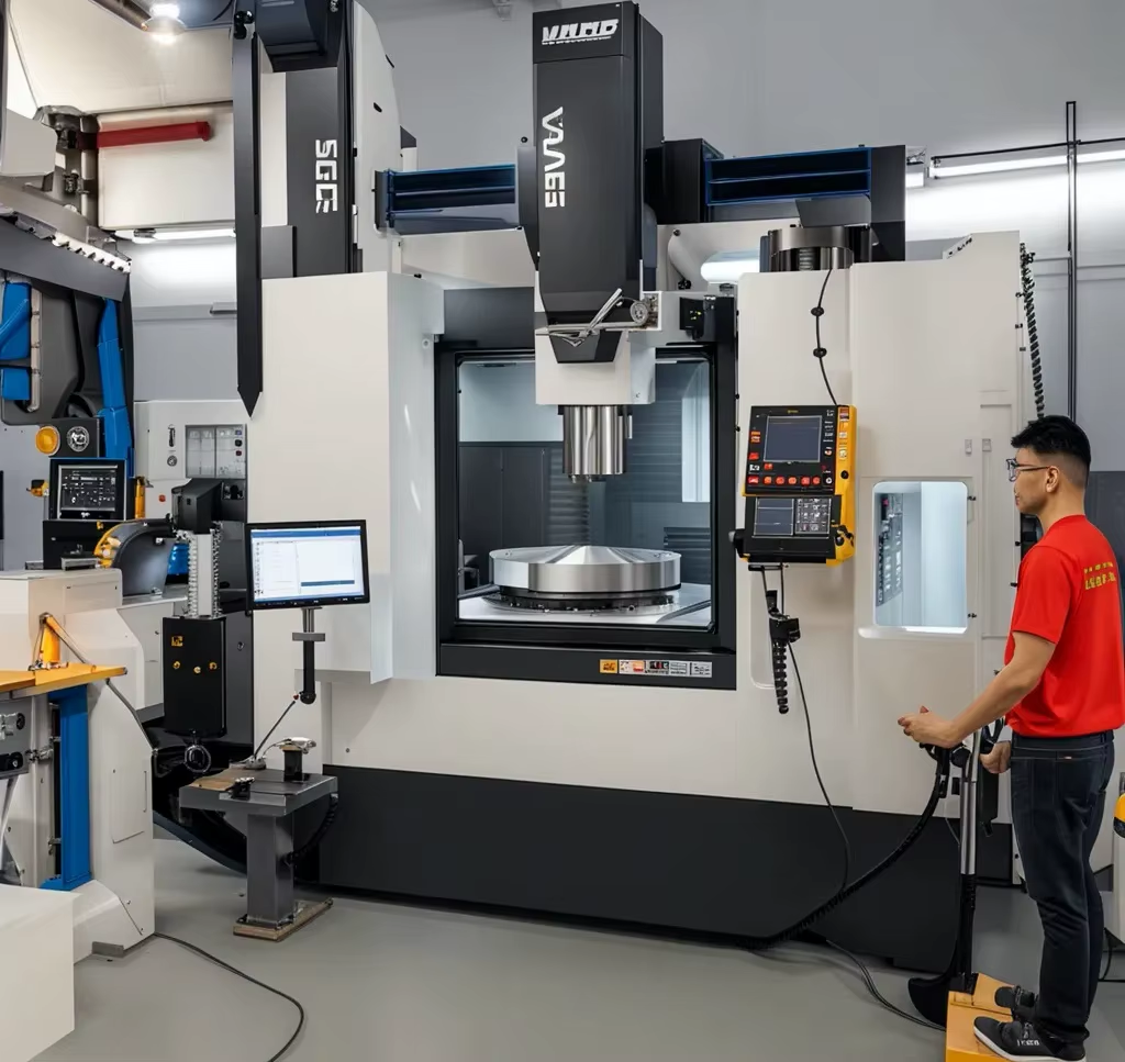
So treat the AMR composite robot as a front-end process, not a replacement for your machining cell. It builds the blank and roughs the shape. Your 5-axis work finishes what the arm cannot hold.
- 1Additive headExtrusion or deposition, layer heights usually 0.5–3 mm
- 2Subtractive headRouting or milling spindle for roughing and hole patterns
- 3Mobile baseRepositions the arm around large, immobile workpieces
- 4Control layerSlicing and toolpath software shared between both heads
Splitting work between the arm and the CNC
The useful question is not whether the arm can machine. It is which features you leave on the arm. Thin walls, large contours, and non-critical mounting pads survive arm-level accuracy. Bearing bores, seal grooves, thread classes, and any face that sets a datum do not.
A practical split looks like this. The arm deposits a near-net shape within 1–2 mm of final. It then roughs the outside profile and drills clearance holes. The part goes to a 5-axis center for datum establishment, critical bores, and finishing passes. This keeps arm time for what the arm does well.
Material choice drives the split too. Short carbon fiber reinforced polymer prints and machines cleanly at the arm. Metal deposition needs a stress relief step before finishing, or the part moves after the last cut. Talk to us before you commit a metal hybrid part to a single setup.
Which features go where
Use this as a starting split, not a rule.
| Feature | Arm (additive + rough) | CNC (finish) |
|---|---|---|
| Near-net blank | Build within 1–2 mm | Datum faces and first op |
| Large contour, thin wall | Yes, single pass | Light finishing only |
| Bearing bore | No | Yes, ±0.005 mm |
| Threaded holes | Pilot only | Tap or thread mill |
| Seal groove | No | Yes, Ra 0.8–1.6 μm |
| Clearance holes | Drill | Ream if fitted |
| Mounting pads | Rough | Face and drill |
| Cosmetic surfaces | Leave stock | Polish or bead blast |
Materials that suit a hybrid cell
Most AMR composite robot work today is polymer and composite. Short and chopped carbon fiber compounds, PA, PEEK, and ABS print with predictable shrinkage. They also cut without the smearing you get on unfilled thermoplastics. For a robot arm link or an end-effector housing, that is often enough.
Metal deposition is the harder case. Titanium and Inconel deposition leaves residual stress that shows up as distortion after milling. If your part is a structural bracket in Ti-6Al-4V, plan a stress relief between the deposit and the finish cuts. Magnesium AZ31B and AZ91D behave better but need chip control and dry handling.
On the CNC side, the finished part still has to match the drawing. We machine aluminium 6061, 7075, 2024, stainless 17-4PH and 316L, tool steel, beryllium copper, and titanium TC4 to the same tolerance whether the blank came off an arm or a billet. The blank source does not change the inspection.
- 1Good fitCarbon fiber reinforced PA and PEEK, ABS, PC
- 2WorkableTi-6Al-4V, Inconel with stress relief
- 3Handle with careMagnesium alloys, unfilled POM, thin PMMA
Holding tolerance after an arm-built blank
A robot arm under load deflects. Reach matters: at 1.5 m from the base, a 2 N cutting force can push the tool a few tenths of a millimetre. That is fine for roughing and fatal for a bore. The fix is to give the arm stock to leave, then let a machine with a rigid column take the last 0.3–0.5 mm.
Datums are the other trap. If the arm-built blank has no flat face and no known hole, the first CNC op becomes a probing exercise. Design two pads and one hole into the blank so the finishing setup can locate it in one pass.
For robot joint housings and arm links, the pattern we see most is: arm deposits the shell, CNC machines both bore ends in one 5-axis setup, then surface finishing follows. That keeps the bore-to-bore alignment inside the ±0.005 mm the joint needs.
Machining specs behind the finishing step
| Item | Value |
|---|---|
| Tolerance | ±0.005 mm (±0.0002 in) |
| Fine finish | Ra 0.2–0.8 μm |
| Standard finish | Ra 0.8–1.6 μm |
| As-machined | Ra 1.6–3.2 μm |
| 5-axis centers | 16 simultaneous |
| Max part size | 4,000 mm |
| Rotary table | Ø400 mm |
| Inspection | 100% before shipment |
Where the hybrid approach pays off
Robotics is the obvious one. Arm links, joint housings, and end-effector bodies are low-volume, geometry-heavy, and change often. Printing a near-net shell and finishing the bores cuts both lead time and material waste against machining from solid.
Aerospace uses the mobile base for large tooling and trim fixtures. A gantry-sized frame does not fit on a machine table, but an arm on a rail can reach it. The critical interfaces still get machined on a 5-axis center afterward.
Automotive and EV teams use it for jigs, check fixtures, and prototype brackets where the shape matters more than the surface. Medical device work is a narrower case: the printed polymer is usually a housing or a handle, and the metal contact parts come off a CNC. If a part touches a patient, keep it on the machine.
Questions engineers ask
Can an AMR composite robot hold ±0.005 mm on its own?
Not on a long reach with a cutting load. The arm's stiffness and thermal drift put it well outside that band.
Use it for near-net build and roughing. Move the part to a 5-axis center for any feature that carries the tolerance.
Does the blank source change how you quote or inspect the part?
No. We machine to the drawing and inspect 100% before shipment, whether the blank was printed, cast, or cut from billet.
Send the 3D model and we return a quotation plus a free DFM analysis within 12 hours.
Which materials can be deposited and then machined?
Carbon fiber reinforced PA and PEEK, ABS, and PC are routine. Ti-6Al-4V and Inconel are possible with a stress relief step between deposition and finishing.
Magnesium alloys need dry handling and chip control, so we treat them case by case.
How do you locate an arm-built blank for the finishing setup?
Design two flat pads and one datum hole into the blank. The first CNC op probes those features and sets the work offset.
Without them, the setup turns into a manual alignment and you lose the tolerance you were trying to protect.
What part sizes can you finish after the arm builds the blank?
Up to 4,000 mm on the largest travel, with 750 × 1,150 × 550 mm and 600 × 600 × 600 mm on the medium machines.
A Ø400 mm rotary table covers most joint housings and round interfaces.
Can you work from a printed shell only, with no solid model of the finished part?
We need the finished geometry, not just the shell, because the finishing toolpaths come from the final surface.
If the shell is all you have, we can start from it and build the finishing model with you.
Send the model, get a machining plan
Upload your part and we return a quotation, a DFM analysis, and a split between arm-level work and CNC finishing within 12 hours.
12-hour quote±0.005 mm100% inspectionNDA on request









