
Automatic terminal design in sheet metal product design
How a terminal actually works inside a product: contact force, bend radius, spring temper, and flat-pattern allowance. Written for mechanical and electrical engineers who need to decide whether a stamped terminal is the right part, and when it is not.
In this article
- 1
- 2
- 3
- 4
- 5
- 6
What a terminal does inside sheet metal product design
A terminal is a spring. It has to hold a mating tab, pin, or wire with enough normal force that contact resistance stays low, and it has to survive being plugged and unplugged. Everything else in sheet metal product design for terminals follows from those two jobs.
When an engineer starts a terminal concept, the first useful question is not which alloy to use. It is how much force the contact needs and how much deflection the spring can take before it yields. A terminal that yields on the first insertion loses its normal force and starts to heat.
Normal force for a small signal contact usually sits between 1 N and 3 N. Power contacts run higher, often 5 N to 15 N, because a loose power contact is a thermal problem, not just a signal problem. The spring beam has to deliver that force across the whole tolerance stack, not only at nominal.
So the design task splits in two. First size the beam so it stays elastic over the full deflection range. Then make sure the stamping and forming process can hold that geometry at volume. Most terminal failures trace back to one of those two being skipped.
Beam geometry: bend radius, width, and free length
A cantilever contact beam behaves like a small leaf spring. Force scales with width and with the cube of thickness, and falls with the cube of free length. A 10 percent increase in free length drops the force by roughly 27 percent, which is why tool wear on the forming punch shows up as contact problems.
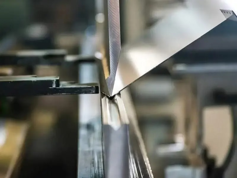
Bend radius matters more than most drawings admit. If the inside radius is smaller than the material thickness, the outer fibers stretch past their elongation limit and the bend cracks or thins. A common shop rule is inside radius at least equal to thickness for soft tempers, and 1.5 to 2 times thickness for hard tempers.
Thinning at the bend also changes the spring rate locally. A bend that comes out at 0.08 mm instead of 0.10 mm is a stiffer hinge than the model assumed, so the beam deflects less and the tip force rises. That is one reason prototypes and production parts can read differently on a force gauge.
Width is your coarse adjustment, thickness is your fine one, and free length is the most sensitive of the three. If a contact is 20 percent off on force, change the beam width in the flat pattern first. Chasing it with a tool grind on the form station is slower and harder to reverse.
Material and temper selection for spring contacts
Copper alloys dominate terminals because they combine conductivity with usable spring properties. C110 (ETP copper) conducts very well but has low yield strength, so it suits fixed busbars more than repeated mating cycles. C26000 brass and C27400 are the workhorses for general contacts.
Beryllium copper is the choice when the contact must keep force at elevated temperature or after many cycles. It costs more and needs tighter process control, but its stress relaxation resistance is far better than brass. Phosphor bronze sits in the middle and is common in consumer connectors.
Temper is the other half of the decision. Half-hard material forms easily and holds a moderate spring. Full-hard gives higher force from the same geometry but cracks at tight radii. The practical compromise is to pick temper from the tightest bend in the part, then size the beam for force.
Stainless 301 and 17-4PH appear in terminals that need corrosion resistance or high temperature capability. They conduct far worse than copper, so they are usually plated or used for mechanical retention rather than current carrying. Do not use stainless for a power contact unless the current is small.
For plating, tin is the default for solderable and separable contacts. Nickel underplate plus gold is used where contact resistance must stay stable at low signal levels. Tin whiskers and fretting are real concerns, and they are a coating decision, not a geometry one.
Flat pattern, springback, and tolerance stack
The flat pattern is where the terminal design is actually decided. Bend allowance and K-factor set the developed length, and a K-factor that is wrong by 0.02 shifts every bend position in the strip. For a 1.0 mm thick part, that is enough to move a contact tip out of position.
Springback is the gap between the tool and the final angle. It grows with yield strength and with the ratio of bend radius to thickness. A 90 degree form in half-hard brass might spring back 1 to 3 degrees; the same form in full-hard material can spring back twice that.
Tolerance stack is where terminal programs quietly fail. Contact position, beam thickness, and mating tab position all have tolerances, and they add. If the nominal deflection is 0.4 mm and the stack is ±0.15 mm, the force at worst case can be half of nominal or double it.
A useful check is to model the contact at minimum and maximum material condition and compare force at both ends. If the low end drops below the force needed for stable contact resistance, either widen the tolerance on the mating part or add compliance to the beam. Adding a second beam in parallel is often cheaper than tightening the stamping.
When stamping is right, and when to machine instead
Stamping wins when the terminal is thin, flat, and needed in volume. Progressive dies hold bend position well, cycle times are short, and the per-part cost falls quickly with quantity. If the part is under about 2 mm thick and the annual volume is in the tens of thousands, stamping is usually the correct route.
Machining wins in the other cases. Thick terminals, small quantities, and parts with geometry that cannot be formed from flat stock are all better cut from bar or plate. A machined terminal can carry a threaded stud, a shoulder, or a pocket that a stamping cannot produce without a secondary operation.
Prototypes sit in between. A laser-cut and press-braked blank gives a real part in days, but its bend radii and springback differ from a production die. Use it to check fit and function, then expect to re-tune force on the first production samples.
GreatLight machines terminal bodies, contact pins, and housings in copper, brass, stainless, and aluminium. Tolerances run to ±0.005 mm on critical features, with 100 percent inspection before shipment. For thin stamped contacts, we can machine the tooling electrodes and prototype blanks that let you test the concept before committing to a die.
Terminal route comparison
Use this to pick a process early. Numbers are typical ranges, not guarantees for every geometry.
| Route | Best thickness | Typical volume | Watch out for |
|---|---|---|---|
| Progressive die stamping | 0.1–2.0 mm | 10,000+ per year | Tool lead time and springback tuning |
| Laser cut + press brake | 0.5–6.0 mm | 1–500 pieces | Different bend radius than production die |
| CNC milling from bar | 3–50 mm | 1–10,000 pieces | Higher unit cost, slower cycle |
| CNC turned contact pin | Ø2–25 mm | 1–10,000 pieces | Needs a forming operation for the spring |
| Wire forming | Ø0.3–3.0 mm | 1,000+ pieces | Limited to round cross sections |
| Die casting plus machining | 2–10 mm walls | 5,000+ pieces | Porosity in thin spring sections |
The short version
If the contact is thin, flat, and high volume, stamp it from half-hard brass or phosphor bronze and tune the beam width. If it is thick, low volume, or needs a machined feature, cut it from bar and keep the spring as a separate formed detail.
Terminal design questions
How do I set the bend radius in the drawing?
Set the inside radius as a range, not a single value, and tie the minimum to the material temper. For half-hard brass at 0.5 mm thick, an inside radius of 0.5 mm to 0.75 mm is workable. Below that, expect cracking on the outer fiber.
Call out the radius on the inside of the bend, because the tooling is built to that surface. If you dimension the outside radius, the shop has to back-calculate and the result drifts.
Why does my contact force drop after a few hundred cycles?
That is stress relaxation, not fatigue. The beam was formed with residual stress, and at temperature it slowly takes a new set. The tip moves, the deflection falls, and normal force falls with it.
Fix it three ways: pick a material with better relaxation resistance such as beryllium copper, reduce the stress in the beam by lengthening it, or stress-relieve the part after forming. Brass at 85 °C will relax noticeably over a few hundred hours.
Can I stamp a terminal with a threaded stud?
Not from flat stock in one operation. The usual answer is a machined insert or a secondary riveting step, which adds cost and a joint that can loosen.
If the stud is load bearing, machine the whole terminal from bar instead. A one-piece part removes the joint and holds concentricity better.
What tolerance can a progressive die hold on bend position?
Bend position typically holds within ±0.05 mm on a well-maintained die at 1 mm thickness. That number drifts as the die wears, so the process needs monitoring, not just an initial buy-off.
Critical contact features should be inspected in process. A 100 percent final inspection catches escapes but will not tell you the die moved last Tuesday.
Does plating change the spring force?
It changes friction at the contact interface, not the beam force. Gold on gold slides with low friction, tin on tin can gall and feel sticky. That difference shows up in insertion force, not in normal force.
For separable contacts, tin is fine at moderate cycle counts. Above a few dozen mating cycles at low signal levels, gold is the safer choice.
When should I move from a machined prototype to a stamped part?
Move when the geometry is frozen and the volume justifies tooling. A machined prototype is for proving force, fit, and assembly sequence.
Before committing, ask for a strip layout review. Most stamping problems are visible in the flat pattern, long before the die is cut.
Send us your terminal drawing
We review the flat pattern, bend radii, and material temper, then return a quote and DFM notes within 12 hours.
12-hour quote100% inspectionNo minimum order quantity
GreatLight on social
We publish setup notes, tooling trials and inspection data from the factory floor.











