
Basic Knowledge of 4 Axis CNC Milling
This page explains how a fourth rotary axis changes milling, which part features actually need it, and where it stops being worth the setup. It is written for design engineers, mechanical engineers and buyers who quote machined parts. After reading it you can look at a drawing and decide whether 4 axis milling is the right process or an unnecessary cost.
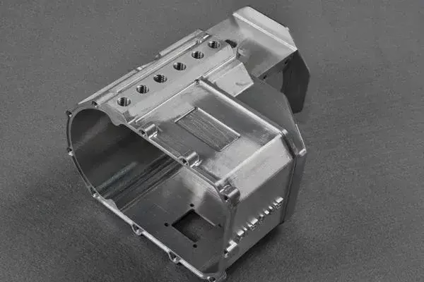
What the fourth axis actually adds
A 3 axis mill moves the tool in X, Y and Z. The workpiece sits still on the table, so only the surfaces facing the spindle can be cut. Turn the part over and you need a second setup: unclamp, re-fixture, re-zero, and accept whatever error the flip introduces.
A 4 axis mill adds one rotary motion, usually called the A axis when it turns about X. The rotary table carries the workpiece and indexes it to a programmed angle, or rotates it continuously while the tool cuts. The spindle still works in three linear axes. What changes is that the part presents new faces to the tool without a human touching the fixture.
That single motion removes a whole class of problems. Holes on four sides of a block, slots around a shaft, flats at 30° intervals, ports on a cylindrical housing: all of these can be cut in one program, one datum, one setup. The geometry is not more complex to machine. It is just presented differently.
Working principle: indexing versus simultaneous rotation
Most 4 axis work is 3+1, meaning the rotary table indexes to an angle, locks, and the cutter mills that face in three axes. This is the workhorse mode. Angles are held by the table's positioning accuracy, not by the operator's shim, so a 90° face really is 90°. Indexing is fast, rigid and easy to program.
True simultaneous 4 axis motion is different. The A axis turns while X, Y and Z interpolate, so the tool tip follows a path wrapped around the part. This is how you cut a helical groove, a cam profile, or an impeller-like surface. It demands a CAM post-processor that understands rotary output and a machine with a controller fast enough to keep the rotary and linear axes in step.
The practical question is whether your feature is a series of flat faces at known angles, or a continuous surface wrapped around an axis. The first is indexing work and suits almost any 4 axis mill. The second needs simultaneous motion, and often a 5 axis machine is the better answer because the tool can also tilt, keeping a short, stiff gauge length.
- 1Indexing (3+1)Table locks at an angle, then mills in three axes. Rigid, simple, repeatable.
- 2Simultaneous 4 axisRotary and linear axes move together. Needed for helical and wrapped contours.
- 3Positioning accuracyAngle tolerance comes from the table, not from the operator.
- 4Datum controlOne work offset covers every face, so stacked tolerances stop adding up.
Which parts belong on a 4 axis mill
The clearest signal is rotational symmetry with features that break the symmetry. A shaft with a keyway, a cross-drilled oil hole and two milled flats is a natural 4 axis part. So is a valve body with ports on several faces, or a manifold block with holes entering from four directions. The part has a dominant axis, and most features are arranged around it.
Cylindrical and prismatic parts with features at defined angles also fit well: hex flats, splines, index pins, wrench flats on a fitting, a slot that must run parallel to an axis over a long length. One rotary setup replaces three or four vise setups, and the angular relationships stay correct because the table holds the reference.
Long parts with a modest diameter are a strong candidate. On a machine with 4,000 mm of X travel and a Ø400 mm rotary table, a long shaft can be supported and rotated while the tool works along its length. That is far more stable than repositioning the part repeatedly along the table.
When 4 axis is the wrong choice
If every feature sits on one accessible face, 3 axis is cheaper and faster. Adding a rotary table adds setup time, a tailstock, sometimes a steady rest, and a slower cycle because the table has mass to accelerate. Do not pay for rotation you never use.
If the part needs undercuts, deep cavities on five faces, or a tool that must reach around a complex boss, a 5 axis machine solves it more cleanly. Simultaneous 5 axis lets the tool tilt, which keeps a short cutter engaged and improves surface finish on curved walls. Forcing that geometry onto a 4 axis machine usually means special cutters and longer run times.
Very large flat plates are also a poor fit. A rotary table consumes the table area you need for clamping, and a heavy plate rotating on a small table invites chatter. Keep 4 axis work on parts that are longer than they are wide, or that are compact and roughly cylindrical.
Thin-walled parts need care in any process. Rotation is generally gentler than flipping a part by hand, but the clamping force of a chuck or collet can still distort a thin ring. Sometimes a soft jaw or an expanding mandrel is the answer, and that decision belongs in the DFM review, not at the machine.
3 axis, 4 axis or 5 axis: matching process to feature
Use the dominant feature pattern to pick the process. Cost and cycle time follow the setup count.
| Part feature | Best process | Why |
|---|---|---|
| All features on one face | 3 axis | No rotation needed; lowest setup cost |
| Holes on 2–4 faces of a block | 4 axis indexing | One datum, angles held by the table |
| Flats, splines, keyways on a shaft | 4 axis indexing | Rotary holds angular position repeatably |
| Helical groove or cam profile | 4 axis simultaneous or 5 axis | Rotary and linear axes must move together |
| Undercuts and deep five-face cavities | 5 axis simultaneous | Tilting tool keeps a short gauge length |
| Large flat plate, many pockets | 3 axis | Rotary table wastes clamping area |
| Thin ring with light features | 4 axis with soft jaws | Gentler than repeated manual flips |
Setup factors that decide the outcome
Workholding comes first. A three-jaw chuck is quick but not concentric enough for tight work. A collet or an expanding mandrel on the rotary table holds better runout. For long shafts, a tailstock supports the free end and a steady rest controls deflection in the middle. Get this wrong and no amount of CAM tuning will save the part.
Datum strategy matters as much as the fixture. With a rotary table, the centerline of the rotation becomes the reference for every face. Dial in that centerline once, and all angular and radial features are measured from it. This is why 4 axis parts often hold ±0.005 mm on hole-to-hole relationships that would drift across multiple 3 axis setups.
Tool reach and rigidity set the practical limit. A long end mill cutting a deep slot on a rotated part will deflect. Keep the gauge length short, use the largest diameter the feature allows, and rough in stages rather than one heavy pass. On stainless and titanium, climb milling and generous coolant flow keep heat out of the part and the edge alive.
Inspection closes the loop. A rotary part usually has features that are hard to reach with a caliper, so a CMM with a rotary table, or a probe on the machine, gives a truer picture. We inspect 100% before shipment and supply reports on request, including first article dimensions and material certificates.
Materials, finishes and typical applications
The process is material-agnostic within reason. Aluminum 6061 and 7075 machine cleanly and suit brackets, housings and prototypes. Stainless 303 and 304 are common for shafts and fittings, while 17-4PH covers higher-strength valve and pump parts. Steel grades such as 1045 and 4140 appear in drive components. Titanium TC4 and Inconel are machinable but demand slower speeds and more attention to tool wear.
Most 4 axis parts get some surface treatment. Anodizing in clear, color or hardcoat is standard for aluminum. Electroless nickel and zinc plating protect steel and copper alloys. Bead blasting, tumbling and polishing are used to deburr and to set a consistent finish. As-machined surfaces sit around Ra 1.6–3.2 μm; finer work reaches Ra 0.8–1.6 μm, and critical sealing faces can be taken to Ra 0.2–0.8 μm.
Typical applications follow the geometry. Automotive and EV parts such as motor shafts, sensor housings and fluid fittings. Aerospace brackets and actuator components. Medical instrument bodies and implant tooling. Robotics joints and gearbox housings. Electronics heat sinks and connector shells. Industrial machinery cams, pulleys and manifolds.
- 1Aluminum6061-T6, 7075, 6082. Fast cutting, good for housings and brackets.
- 2Stainless and steel303, 304, 17-4PH, 4140. Shafts, valves, drive parts.
- 3Titanium and specialTC4, Inconel. Slower speeds, tighter tool-wear control.
- 4PlasticsPOM, PEEK, ABS. Light cuts to avoid melting and burrs.
4 axis CNC milling questions engineers ask
Is the fourth axis always the A axis?
Not always. The rotary axis is named by the linear axis it turns about. Rotation about X is A, about Y is B, about Z is C.
On most vertical mills the fourth axis is A, mounted so the part turns about the X axis. Horizontal machines and mill-turn centers often use B or C. What matters for your drawing is which machine axis the part rotates about, because that defines the centerline your dimensions reference.
Can a 4 axis mill cut a true helical groove?
Yes, if the machine supports simultaneous motion and the CAM post handles rotary output. The rotary table turns continuously while X, Y and Z interpolate, producing a wrapped path.
The limit is usually rigidity, not the controller. A long, thin cutter engaged in a deep helical slot will deflect. Where the groove is shallow and the tool is stiff, 4 axis simultaneous work is reliable and repeatable.
How much does a rotary table improve angular accuracy?
It removes the human step. On a 3 axis mill, a 45° face depends on how well the operator indicates the part after a flip. On a rotary table, the angle is a programmed position held by the table.
That is why multi-face parts often tighten from a few hundredths of a millimeter to ±0.005 mm on angular and radial relationships. The gain comes from the datum, not from a better cutter.
Do I need a tailstock for every 4 axis job?
No. Short, compact parts held in a chuck or collet usually need only the rotary table. A tailstock is for long parts where the free end would deflect or vibrate.
For very long shafts, a steady rest supports the middle as well. The fixture plan follows the length-to-diameter ratio: the slimmer the part, the more support it needs.
What tolerance and finish can 4 axis milling hold?
Our 4 axis work targets ±0.005 mm (±0.0002 in) on critical dimensions, with as-machined surfaces around Ra 1.6–3.2 μm.
Where a drawing calls for it, finishing passes reach Ra 0.8–1.6 μm, and sealing or bearing faces can be taken to Ra 0.2–0.8 μm. We inspect 100% before shipment and supply reports on request.
How do I know if my part should be quoted as 4 axis?
Send the 3D model and 2D drawing with tolerances and material. We review the feature pattern and tell you which process fits, including where 3 axis is enough and where 5 axis is the better route.
Quotation and a free DFM analysis come back within 12 hours. Uploads stay confidential, and an NDA is available on request.
Send your part, get a process recommendation
Upload your model and drawing. We review the geometry, tell you whether 4 axis milling is the right fit, and return a quotation with free DFM feedback within 12 hours.
12-hour quoteFree DFM analysisNo minimum order quantityNDA on request









