
Basic Knowledge of the Five Axis Linkage Machining Center
This page explains how a five-axis linkage machining center actually moves, what the two common machine layouts are good at, and which parts belong on one. It is written for design engineers and buyers who need to decide between five-axis linkage and a 3-axis machine with extra setups.
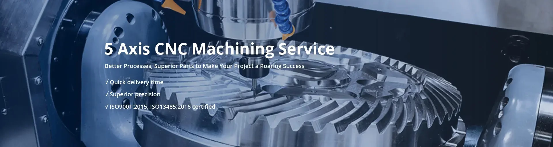
What the fifth axis buys you
Five-axis linkage is not five separate movements stacked together. It is linear and rotary axes cutting at the same time.
The three linear axes and the two rotary axes
Every machining center starts with X, Y and Z. The spindle or the table moves along these three linear axes. A five-axis machine adds two rotary axes on top of that. The common naming is A and B for rotation around the X and Y axes, and C for rotation around Z.
Linkage means those rotary axes move while the tool is in the cut. The controller keeps the tool tip on the intended path as the part or the head tilts. That is why a five-axis linkage machine can cut a curved surface in one continuous pass instead of a series of indexed positions.
The payoff shows up on parts with compound angles, deep pockets on several faces, or ruled surfaces that would need a ball nose tool to sweep line by line on a 3-axis machine. A shorter, stiffer tool reaches further into the part because the table or head positions the work for you.
- 1X, Y, ZLinear travel. Define the working envelope and the maximum part size.
- 2A and BRotary axes around X and Y. Tilt the head or the trunnion.
- 3CRotation around Z. Usually the table, range ±360°.
- 4SimultaneousAt least four axes commanded in the same block. This is the real dividing line.
Swing-head machines versus rotary-table machines
Two layouts dominate five-axis work, and they are not interchangeable. On a swing-head machine, the spindle head carries the two rotary axes, so the part stays on a fixed bed. The A axis typically swings about +30° to -120°, and the C axis under the head turns ±360°. Because the part does not move, heavy and awkward blanks are easier to clamp.
On a rotary-table machine, the part sits on a trunnion or a tilting table. The table rotates around Z and tilts around X or Y, and the spindle stays simpler and stiffer. The trade is load. A Ø400 mm rotary table has a real weight limit, and a 300 kg casting is not going on it. Table machines are the better fit for smaller, high-mix parts that need five faces cut in one setup.
Neither layout is a general upgrade. If your part is a 900 mm weldment with one angled face, a swing-head machine with a large envelope does the job. If it is a 120 mm aluminium housing with ports on four sides, the rotary table wins on cycle time and rigidity.
At GreatLight we run both. Sixteen simultaneous five-axis machining centers sit alongside 12 four-axis mills and 27 three-axis machines, so the routing follows the part instead of the other way around.
- 1Swing headPart stays still. Handles heavier and larger workpieces.
- 2Rotary tablePart tilts. Better rigidity and access on small parts.
- 3TrunnionTwo rotary axes under the part. Common on compact cells.
- 4Ø400 mm tableTypical rotary platform in our five-axis fleet.
When five-axis linkage is worth it, and when it is not
The case for five-axis linkage is usually setup count, not raw speed. A part with features on five faces machined on a 3-axis mill needs four or five re-clamps. Each re-clamp adds a datum shift, an operator decision, and an inspection step. One five-axis setup removes most of that stack-up.
Accuracy follows the same logic. Once a part is cut in a single fixture, the relationship between a bore on one face and a slot on another comes from the machine, not from how carefully somebody tapped it back against a stop. That is where we hold ±0.005 mm on position between features, not just on a single dimension.
There are cases where five-axis is the wrong call. Simple prismatic parts with features on two faces cut faster on a 3-axis machine, and the hourly rate is lower. Very large parts can exceed the envelope or the table load. Deep, narrow cavities can still favor a 3-axis machine with a long reach tool if the geometry does not need tilting at all.
A useful test before quoting: count the setups, then count the features that sit off the main axes. If the answer is three setups and one angled hole, ask whether a fixture can solve it cheaper. If it is five setups and a network of intersecting ports, five-axis linkage is the low-risk route.
Five-axis linkage versus 3-axis with extra setups
Use this as a first screen, not a final quote.
| Part condition | Five-axis linkage | 3-axis + fixtures |
|---|---|---|
| Features on 4–5 faces | One setup, best fit | 3–5 setups, more error stack-up |
| Two faces only | Works, but rate is higher | Lower cost, faster cycle |
| Compound angled holes | Tilt and drill in position | Angled fixture or EDM |
| Part mass over ~200 kg | Swing head only | Standard vise or tombstone |
| Tight feature-to-feature tolerance | Single datum, more repeatable | Datum shifts stack up |
| Short prototype run | No fixture cost | Fixture build may not pay off |
The limits nobody mentions in the brochure
Five-axis machines trade working volume for reach. The rotary axes and the trunnion eat space inside the envelope. A machine listed at 600 × 600 × 600 mm will not cut a 600 mm cube on all faces, because the corners swing outside the travel. Always check the usable volume at the tilt angles your part actually needs.
Load capacity is the second limit. Rotary tables are rated for a mass and a moment. A part that passes the weight check can still fail the moment check if it hangs far from the table center. Long shafts and offset brackets are the usual offenders.
Thermal behavior matters more here than on a 3-axis machine. The rotary axes add heat sources and more geometry that can drift as the shop warms up. We rough, let the part and the machine settle, then finish. On tight work the finishing pass runs after a temperature soak, not straight off the roughing cycle.
Tool access is the last constraint. Tilting the part can put a wall between the tool holder and the surface, or swing the holder into the fixture. Simulation in the CAM package catches most of this before the first cut, and we verify the holder and the fixture model, not just the tool.
- 1Usable volumeCheck travel at the tilt angles you need, not at zero tilt.
- 2Table momentWeight and offset both matter. Long parts fail the moment check.
- 3Thermal driftRough, soak, then finish on tight tolerances.
- 4Holder collisionSimulate the holder and fixture, not only the cutter.
What we cut on the five-axis centers
Aluminium is the common case: 6061, 7075, 2024 and 6082 for housings, brackets and manifolds. These cut fast and hold tight tolerances well, so the five-axis setup usually pays for itself through setup reduction alone.
Stainless and titanium change the math. 17-4PH, 316L, TC4 and Inconel push cutting forces and heat up, so we slow the rotary feed and watch tool wear between parts. Five-axis still helps because the tool stays engaged at a consistent angle instead of chattering at the edge of its reach.
Surface finish is set by the finishing strategy, not by the axis count. We hold Ra 0.8–1.6 μm on typical machined surfaces and Ra 0.2–0.8 μm where the drawing calls for it. Anodizing, electroless nickel, bead blasting and laser marking are available after machining, with a minimum character height of 1.5 mm for marking.
Certification coverage matters if your part ships into a regulated supply chain. We hold ISO 9001:2015, IATF 16949:2016, ISO 13485:2016 and ISO 27001:2022, and every part gets 100% inspection before shipment with reports on request.
Questions engineers ask before sending a five-axis part
What is the difference between 5-axis and 5-axis linkage?
A machine can have five axes and still run them indexed, meaning the rotary axes move to a position and lock before the cut starts. That is often called 3+2.
Linkage means the rotary axes move while the tool is cutting. This is what allows a continuous swept surface and what makes the controller do real-time compensation. If a shop says five-axis, ask which one they mean.
What size parts can you handle on the five-axis machines?
Our maximum processing size reaches 4,000 mm, and the large travel is 4,000 × 400 × 150 mm. Medium platforms run 750 × 1,150 × 550 mm and 600 × 600 × 600 mm.
Compact cells use 500 × 500 × 450 mm and 500 × 310 × 200 mm with a Ø400 mm rotary table. Send the drawing and we will confirm which platform fits, including usable volume at your tilt angles.
Does five-axis always cost more per part?
Not necessarily. The machine rate is higher, but you remove setups, fixture builds and re-clamp risk. On a part with features on five faces, the total often comes out lower than the 3-axis route.
On a simple two-face part the 3-axis route stays cheaper. We quote both when the geometry is borderline and let the numbers decide.
How do you hold tolerance across several faces?
The part stays in one fixture, so feature-to-feature position comes from the machine geometry rather than from re-clamping. We hold ±0.005 mm on position, with a raw material check, in-process monitoring and a final inspection.
For tight work we rough, allow the part and machine to reach thermal stability, then run the finishing pass.
What is the smallest order you take?
There is no minimum order quantity. We run from one prototype to 10,000+ part runs on the same process, so the first article and the production run follow the same routing.
Quotation and a free DFM analysis come back within 12 hours, and production can start within 24 hours once the drawing and material are confirmed.
Will you sign an NDA before I send drawings?
Yes. Uploads are secure and confidential, and an NDA is available on request before you share files.
If your program needs it, we can also work under your own NDA template.
Send the drawing, get a routing opinion
Tell us the part size, the faces you need cut and the tolerance. We will say whether five-axis linkage is the right route, and quote it either way.
12-hour quote100% inspectionNo minimum order quantityNDA on request









