
Carbon CNC Precision Processing
This page is for engineers and buyers who need machined carbon fiber reinforced polymer parts, not molded shells. It covers what makes CFRP different from metal on the shop floor, where the tolerance limits sit, and which part geometries belong on a 5-axis machine.
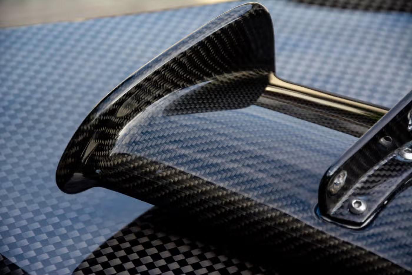
Why CFRP Machines Differently From Aluminum
A carbon fiber laminate is not a homogeneous block. It is stacked plies with a resin matrix, and its properties change direction: strong along the fiber, weaker across it. When a cutter pushes into that stack, the load path is uneven. The edge can break out before the tool reaches full depth.
Carbon fiber is abrasive. The fiber itself is harder than most tool steels, so edges dull fast. A cutter that holds size in 6061 for hours may lose its edge in CFRP within a short run. Dull tools raise cutting temperature, and hot resin smears rather than shears. That is where burrs and frayed edges start.
Heat does not leave the cut the way it does in aluminum. CFRP conducts poorly, so the tool tip keeps the heat. The resin softens near the glass transition temperature, and the bond between fiber and matrix weakens. Once that happens, the surface tears instead of cutting clean.
Chips are another issue. Carbon dust is fine, light, and conductive. It gets into way covers, spindle tapers, and coolant lines. Any shop running carbon CNC precision processing needs extraction at the cut and a cleaning routine between jobs, or the next steel part inherits carbon grit.
Delamination, Fiber Pull-Out, and How to Read Them
Delamination is the failure that matters most. It shows as a white or gray patch along a machined edge, or as a lifted ply on an exit face. It comes from axial force pushing the top plies away from the ones below. The fix is usually geometry, not force: a sharper tool, a smaller step-down, and a climb cut that keeps the fiber in compression.
Fiber pull-out looks different. You see individual strands left standing at the edge, like a brush. It usually means the tool is dull, the feed per tooth is too low, or the resin has softened. Running the cutter so it rubs instead of bites is a common mistake in carbon CNC precision processing. A light, fast pass cuts cleaner than a slow, heavy one.
Fraying on the bottom face is an exit-side problem. The support is gone by the time the tool breaks through. A backing plate, a sacrificial layer, or a change in tool path direction usually solves it. The tool should exit into scrap material, not into open air.
Hole quality follows the same logic. Peck drilling and helical interpolation both reduce thrust. For a hole that will carry a fastener, the edge condition matters as much as the diameter. A drill with a 8-facet or dagger geometry is a better choice than a standard 118° point.
Matching the Machine and Tool to the Feature
Use this as a starting point, not a fixed rule. The laminate layup and part stiffness matter as much as the feature itself.
| Feature | Typical machine | Tool note |
|---|---|---|
| Flat pocket, open face | 3-axis | Diamond-coated router, climb cut |
| Contoured skin panel | 5-axis | Ball or bull nose, small step-down |
| Deep hole, Ø6 mm and under | 3-axis or mill-turn | Dagger drill, peck cycle |
| Trimmed edge on curved part | 5-axis | Compression router, backing plate |
| Thin wall under 2 mm | 5-axis | Light radial engagement, high spindle speed |
| Fastener hole pattern | 3-axis | Helical interpolation after spot drill |
Tolerances, Finish, and Where the Limits Sit
We hold ±0.005 mm on machined features where the geometry allows it. That number is real, but it depends on the part. A rigid, well-supported feature on a cured laminate can hold it. A thin, unsupported flange will move when the clamps come off, no matter how good the cut was.
Surface finish is a separate target. As-machined CFRP typically sits at Ra 1.6–3.2 μm. With a sharp tool and light finishing passes, Ra 0.8–1.6 μm is realistic. Ra 0.2–0.8 μm is reachable on selected faces, usually after a finishing pass with a new cutter. The limit is often the laminate itself, not the machine.
The maximum processing size is 4,000 mm, with travels of 4,000 × 400 × 150 mm on the large machines. Medium platforms cover 750 × 1,150 × 550 mm and 600 × 600 × 600 mm. Compact platforms run 500 × 500 × 450 mm and 500 × 310 × 200 mm. A Ø400 mm rotary table handles parts that need indexing.
Inspection matters more here than in metal. Carbon parts can pass a go/no-go gauge and still have a delaminated edge. We check raw material, monitor in process, and inspect 100% before shipment. Reports are available on request. The qualification rate across our carbon and metal work is 99.99%.
Fixturing, Dust Control, and Tool Life
Fixturing is where most carbon jobs succeed or fail. Clamping pressure that would be fine on aluminum can crush a honeycomb core or close a thin laminate. We use vacuum chucks, dedicated soft jaws, and where needed, sacrificial backing plates that support the exit face. A part that reads true on the machine can spring when released, so we plan the workholding around how the part will relax.
Tool life in CFRP is shorter and less predictable than in aluminum. Diamond-coated carbide gives the best cost per part on long runs. Polycrystalline diamond (PCD) holds up even better in abrasive laminates, but the entry cost is higher. On short prototype runs, a sharp uncoated carbide cutter can be enough if the operator changes it before it dulls.
Dust extraction runs at the cut, not in the room. A localized nozzle near the tool tip catches most of the fines. The rest gets handled by enclosure cleaning between jobs. Carbon dust left on a machine will contaminate the next part, and if that part is for a medical or food application, it is a real problem.
Coolant is a judgment call. Some shops run CFRP dry, others use a mist. Dry cutting keeps the part clean, but heat builds at the tip. Mist controls heat but needs a capture system. We pick per job, based on the laminate, the feature, and the finish target.
When Carbon Is the Right Choice, and When It Is Not
Carbon fiber earns its cost when stiffness-to-weight or strength-to-weight drives the design. Aerospace brackets, drone arms, automotive and EV structural parts, and robot links are the usual cases. If the part saves mass and keeps stiffness, CFRP is often the only material that meets the load case without adding weight.
It is a poor fit when the part is mostly a mounting plate with no weight target, or when the geometry needs deep pockets and sharp internal corners. Carbon does not like sharp inside corners, because the fiber does not turn that tightly. A radius is cheaper than a redesign later.
It is also a poor fit when the part will see high point loads through a threaded hole. CFRP does not take a thread the way aluminum does. Inserts, bonded bosses, or through-bolts with washers are the normal fix. Designing those in from the start saves a revision.
We machine carbon fiber alongside aluminum, stainless, titanium, and engineering plastics. That matters when a part is a mixed assembly. Brackets in 6061 or 7075, fasteners in 316 stainless, and the structural member in CFRP can all come from one shop with one inspection sheet.
Common Questions on Carbon CNC Precision Processing
Can you hold ±0.005 mm on a carbon fiber part?
On rigid, supported features, yes. The tolerance depends on the laminate and the geometry. A thick, well-backed wall holds it. A thin flange that deflects under clamping force will not, and we will tell you that before cutting.
We inspect 100% before shipment and can supply reports on request.
Do you machine CFRP dry or with coolant?
Both, depending on the job. Dry cutting keeps the part clean and avoids fluid trapped in the laminate. Mist and coolant control heat at the tool tip but need extraction.
The choice follows the feature, the finish target, and the laminate layup.
What is the largest carbon part you can machine?
Up to 4,000 mm on the large platforms, with travels of 4,000 × 400 × 150 mm. Medium machines cover 750 × 1,150 × 550 mm and 600 × 600 × 600 mm.
If your part is longer than the travel, we can discuss splitting the operation or a different process.
How do you keep carbon dust out of other jobs?
Extraction at the cut, enclosure cleaning between jobs, and separate handling for abrasive laminates. Carbon fines are conductive, so they cannot be left on ways or tapers.
This is part of the standard setup for any carbon run.
Can you machine a carbon part with metal inserts bonded in?
Yes, and it is common. Inserts let you use threads that CFRP cannot hold on its own. The insert is bonded or potted before final machining, and we cut the carbon around it.
Tell us the insert type and the bond line requirement at the quote stage.
What lead time should I expect?
Quotation and a free DFM analysis come back within 12 hours. Production can start within 24 hours of order release, and parts ship in 3–5 days.
There is no minimum order quantity. One prototype or a 10,000+ part run both work.
Send the STEP File and the Layup
We will review the geometry, flag the features that are hard to cut in CFRP, and quote within 12 hours. Uploads stay confidential and an NDA is available on request.
12-hour quoteFree DFM analysis100% inspectionNo minimum order quantity









