
Carbon fiber CNC processing for structural and prototype parts
This page explains how we cut carbon fiber reinforced polymer on CNC equipment, which parts suit machining and which do not, and what drives cost and tool life. It is written for design engineers and sourcing engineers who need to compare carbon fiber CNC processing against molding or hand layup before releasing a drawing.
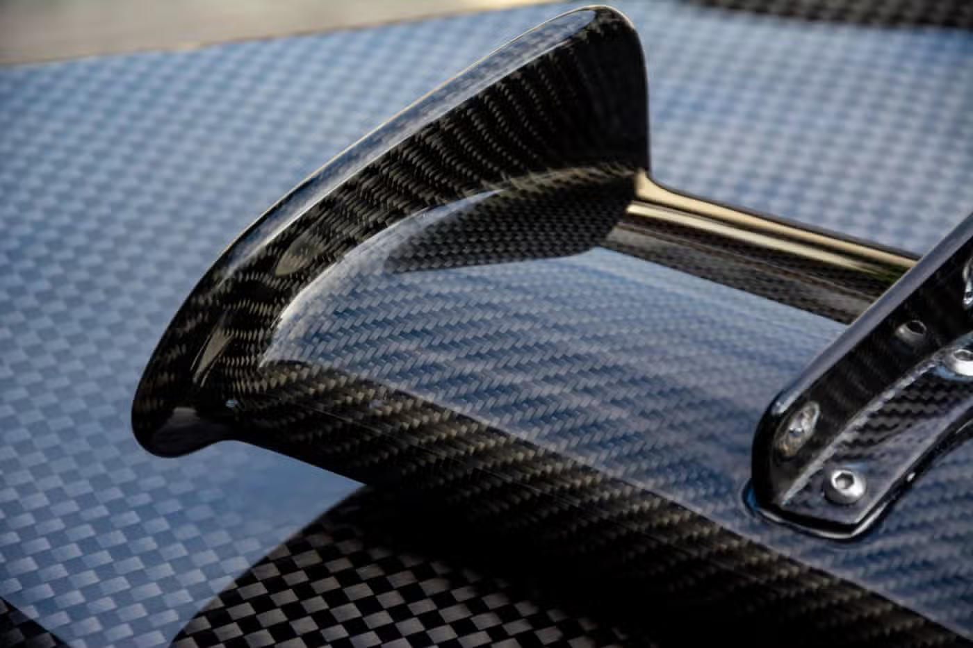
What carbon fiber CNC processing actually removes
CFRP parts are usually molded near net shape. Machining is the step that brings them to tolerance.
The material you are cutting is not one material
The workpiece is a laminate, not a homogeneous block. Half of it is fiber that is harder than high-speed steel, and the other half is a polymer matrix that is soft, abrasive and heat sensitive. A cutter meets both at the same time. That is why carbon fiber CNC processing behaves nothing like aluminum or steel, where the chip carries most of the heat away.
Fiber direction matters more than most drawings show. A cut along the fiber path produces a clean edge. A cut across it lifts fibers instead of shearing them, and the frayed wall shows up on the finished part. Ask for a laminate schedule with ply orientation before quoting.
Three grades cover most work we see. Standard modulus (230–240 GPa) is the general-purpose choice. Intermediate modulus buys stiffness at roughly 20–30% higher material cost. High modulus (350 GPa and up) is brittle, splinters easily and is usually worth machining only when stiffness is the whole point.
Thickness sets the rules. Below 1 mm, clamping pressure alone can bow a panel. Above 6 mm, tool wear and heat buildup dominate the cost. Between those, the process is predictable.
How we set up and cut a CFRP part
Diamond-coated tooling is the default. Uncoated carbide dies within a few minutes in abrasive laminate. We run polycrystalline diamond (PCD) or diamond-coated end mills with 2 to 4 flutes, high helix, and a sharp positive rake. Tool life still runs shorter than in aluminum, so we budget for changes mid-run.
Spindle speed and feed are pushed, not eased. Too slow and the resin smears and burns; the heat has nowhere to go. We keep the chipload high enough to shear fiber cleanly and use climb milling for the finish pass to reduce delamination at the exit edge.
Dust extraction runs the whole time. CFRP dust is conductive and a respiratory hazard, so machines cutting it are fitted with wet or dry extraction and the operator wears protection. We do not cut carbon fiber on a machine that will run the same day on a medical implant without a full clean-down.
Clamping is where thin panels go wrong. Vacuum fixtures or a sacrificial backing plate support the part across its full area. Point clamping on a 2 mm skin will flex it and give you a part that measures right on the machine and wrong on the CMM.
Coolant is usually air or mist, not flood. Flood coolant can wick into an exposed laminate edge and stay there. For most CFRP work we cut dry with air blast and manage heat through feed and tool geometry.
CFRP machining parameters and limits
Typical values for the work we quote most often. Exact numbers depend on ply layup and part geometry.
| Item | Typical range | Notes |
|---|---|---|
| Tolerance | ±0.005 mm | Achievable on rigid, well-supported parts |
| Surface finish | Ra 0.8–1.6 μm | Standard machined finish on CFRP |
| Fine finish | Ra 0.2–0.8 μm | Needs a separate finishing pass |
| Panel thickness | 0.8–6 mm | Outside this, discuss before quoting |
| Tooling | PCD or diamond-coated | Uncoated carbide wears too fast |
| Flutes | 2–4, high helix | Chip clearance matters more than rigidity |
| Maximum part size | 4,000 mm | On our large-format 5-axis centers |
| Edge quality | Climb milling finish pass | Reduces fiber pull-out at exit |
| Inspection | 100% before shipment | Reports on request |
Machining versus molding and hand layup
Use molding when you are making the same part hundreds of times and the shape is fixed. A matched metal mold spreads its cost over the run and gives you a smooth surface without cutting fiber. The tooling lead time is the trade-off.
Choose machining for prototypes, one-off fixtures, trimmed edges, drilled holes, and any feature the mold cannot form. Carbon fiber CNC processing is also the practical route when a design is still moving, because a program change costs far less than a mold change.
Hybrid runs are common. A part is molded oversize, then machined to final tolerance on the mating faces and hole patterns. This is the usual pattern for aerospace brackets and EV battery structures, where the molded skin is fine but the bolt holes and bushings must be exact.
Design details that decide whether the part machines well
Keep wall thickness as uniform as you can. A sudden change from 3 mm to 8 mm creates a heat sink and a stiffness step, and the cutter will deflect at the transition. A gradual taper costs nothing in the drawing and saves scrap.
Give every hole a pilot or a drill cycle. Drilling straight into laminate with a standard twist drill splits plies on the exit side. We use backing plates or step drills, and we keep hole diameter at least 1× the material thickness to avoid breakout.
Radius internal corners. A sharp inside corner needs a small cutter, and a small cutter in abrasive laminate breaks or wears out mid-feature. A 1 mm corner radius lets us use a stiffer tool and hold the tolerance.
Do not design exposed fiber end grain where a seal or thread will sit. Exposed ends wick moisture and do not hold torque well. Add a machined insert pocket or a bonded bushing instead.
Inspection and what we send with the parts
Every part is inspected before shipment. For CFRP that means checking hole diameters, edge quality and any critical face flatness against the drawing. Delamination is not always visible, so we inspect after the finishing pass rather than before.
We check raw material on arrival, monitor in-process dimensions, and run a final inspection. Reports are available on request. Our tolerance floor is ±0.005 mm and our historical qualification rate is 99.99%, both of which hold only when the part is properly supported during cutting.
Certifications cover ISO 9001:2015, IATF 16949:2016, ISO 13485:2016 and ISO 27001:2022. The last one matters if your drawings are controlled. Uploads are handled as confidential and we sign an NDA on request.
Common questions from engineers
Can you machine carbon fiber and metal on the same machine?
We can, but not back to back without a full clean-down. CFRP dust is conductive and abrasive, and a trace of it in a medical or electronics job is a defect. Machines are scheduled so carbon work is separated from sensitive runs.
If your part is a carbon-metal assembly, we usually machine the metal components and the CFRP separately, then assemble. That keeps tolerances clean and avoids cross-contamination.
What tolerance can you actually hold on a thin panel?
On a well-supported panel above 2 mm, ±0.005 mm is realistic on hole positions and machined edges. Below 2 mm, the part deflects under clamping and cutting force, so the practical floor loosens.
The fix is a vacuum fixture or a sacrificial backing plate. Tell us the panel thickness at quote stage and we will say what is achievable rather than promise a number we cannot hold.
Does machining cut the fibers and weaken the part?
It cuts fibers at the machined edge, and that edge loses some strength compared with a molded edge. For most brackets and housings the loss is local and acceptable.
For highly loaded edges, we can leave a molded margin, add a ply drop, or specify a finishing pass that reduces pull-out. If the edge is a primary load path, say so on the drawing.
How do you handle the dust?
Extraction runs during cutting, and operators wear respiratory protection. We use wet or dry extraction depending on the machine and the part size.
Carbon dust is conductive, so it is kept away from electronics and from any machine that will run a sensitive job next.
Can you finish a CFRP part after machining?
Yes. We offer bead blasting, sanding, polishing, painting and powder coating, and laser marking with a minimum character height of 1.5 mm.
Masking matters. Machined edges and insert pockets usually need protection before any coating step, so mark those areas on the drawing.
What do you need to quote a CFRP part?
A 3D model or 2D drawing with tolerances, the laminate schedule if you have one, panel thickness, and the quantity. If the layup is not fixed, tell us the stiffness target and we will work from that.
Quotation and a free DFM analysis come back within 12 hours. There is no minimum order quantity, so a single prototype is fine.
Send us your CFRP drawing
Upload a model or drawing and we will return a quote with a DFM note on thickness, tooling and edge quality within 12 hours.
12-hour quote100% inspectionNo minimum order quantityNDA on request









