
CNC machining and casting: how the two processes shape a metal part
Casting sets the near-net shape, CNC machining sets the final tolerance. This page explains where each process stops, what the part inherits from the mold, and how to pick a route before you cut a purchase order.
In this article
- 1
- 2
- 3
- 4
- 5
- 6
- 7
What casting actually gives you before any CNC machining starts
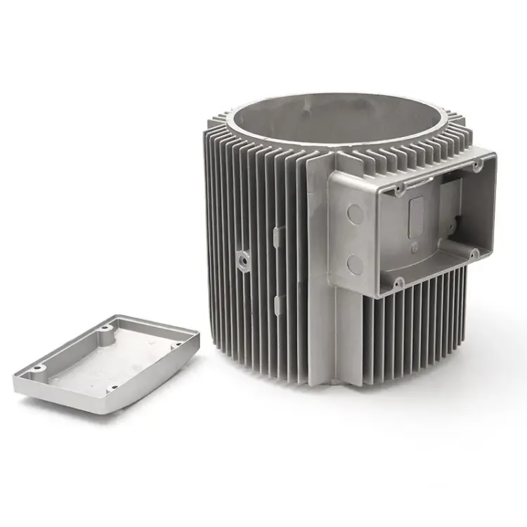
Casting is a shaping process, not a sizing process. Metal is melted, poured or injected into a cavity, and solidifies against the mold wall. The part that drops out already has its overall form: bosses, ribs, internal passages, draft angles, fillets. Nothing about that shape is cut. It is copied from the cavity.
The copy is never exact. Every metal shrinks as it cools, and different sections of the same part cool at different rates. A thick boss pulls more than a thin web next to it. Mold wear adds a slow drift over the tool life. So the as-cast part carries a tolerance band that is loose compared with machining, and the band is not uniform across the part.
That is why the two processes are usually paired rather than opposed. Casting does the rough shaping where removing metal would be slow and wasteful. CNC machining then cuts the surfaces that must actually fit something: bores, sealing faces, bolt patterns, bearing seats. The casting decides what the part is. The machining decides whether it works.
One more thing worth knowing early. Cast surfaces are not machined surfaces. A casting that looks fine can still hide porosity, cold shuts or shrinkage voids under the skin. If a bore is going to see pressure or fatigue, you want enough machining allowance to cut past that skin.
Where CNC machining and casting each run out of road
Casting wins on shape complexity per unit of cost. An internal cooling channel, an undercut, a wall that tapers from 8 mm to 3 mm: all of these are free in a mold and expensive on a mill. Once the tooling exists, the per-part cost falls fast with volume, because the cycle time is a pour or an injection, not a toolpath.
Machining wins on dimensional control. On a 5-axis center we hold ±0.005 mm (±0.0002 in) and surface finishes down to Ra 0.2–0.8 μm. No casting process reaches that. Machining also wins on change. There is no hard tooling to modify, so a revised drawing becomes a revised program.
The failure mode to watch is asking casting to hold a feature it cannot. Deep small bores, sharp internal corners, threads, tight flatness over a large face: these usually come out of the mold as stock and get finished by cutting. If you design them as-cast, you will be reworking parts or living with the fallout.
The reverse mistake is machining a part that should have been cast. If 70 percent of the stock is coming off as chips on a part with a complex organic shape, you are paying machining hours for geometry a mold would have given you. At low volume that is still the right call. At high volume it is usually not.
Material choice shifts the line too. Aluminum and zinc die casting run at moderate temperatures with long mold life. Titanium and Inconel do not cast cheaply at all, so those parts are often cut from solid plate even when the shape is complex.
How the mold is cut, and why that step decides your tolerance
The mold itself is a machined part, and it is usually cut on the same kind of equipment that will later finish the castings. Cavity and core inserts are milled, EDM'd where the geometry needs sharp internal corners, then polished. We cut mold inserts on 3-axis and 4-axis mills, with 5-axis work for contoured parting surfaces and deep ribs.
This is the part most buyers miss. The tolerance of a casting is partly the tolerance of the mold, amplified by shrinkage and wear. If the cavity is off by 0.02 mm, every part from that cavity inherits the error. Gate location, cooling line placement and venting are set at the same time, and they control porosity and weld lines as much as the alloy does.
Draft is the second thing set at this stage. Every vertical wall in the cavity needs a release angle, typically 1–3° depending on depth and surface finish. No draft means the part tears or drags on ejection. A designer who sends a zero-draft model will get a mold that has been quietly modified, and the casting will not match the CAD.
So the sequence matters. DFM review happens before the cavity is cut, not after. We check wall thickness, draft, radii, machining allowance and gate position while the geometry is still cheap to change. Quotation and free DFM analysis come back within 12 hours, and production can start within 24 hours once the drawing is frozen.
Machining allowance: how much stock the casting must leave
Machining allowance is the layer of metal left on a cast surface so the cutter has something to remove. It is not a guess. It is set by the casting tolerance plus the flatness and location error you expect, plus a margin for the surface skin you want to cut through.
For sand and gravity castings, 2–3 mm per machined face is normal. Die castings hold tighter, so 0.5–1.0 mm is often enough, and 0.3 mm can work on a well-controlled face. Investment castings sit between those numbers. If the allowance is too small, the cutter skims and leaves raw cast skin in a low spot. If it is too large, you pay for the extra roughing pass and lose cycle time.
Location is the harder half of the problem. A casting has no natural datum. You fixture it on cast pads or bosses and reference from there, so the first operation decides where every later surface lands. If the cast datum pad itself varies by 1 mm, the machined bore may run out of position even though its own diameter is perfect.
The usual fix is to machine the datum first, in one setup, and then work from it. Where that is not possible, we design the allowance so the worst-case stack still leaves 0.2–0.3 mm of clean-up on every critical face. That number is what keeps a production run from drifting into scrap.
For prototypes and small runs, machining from solid usually beats building tooling. There is no mold to fund, no draft to add, and no allowance to reason about. You get the geometry you drew, at full tolerance, in days.
When porosity or a bad surface shows up after machining
Porosity is the casting defect that reaches the machined part. Gas trapped during fill, or shrinkage as a thick section solidifies, leaves voids below the skin. Nothing shows on the raw casting. Then a face is cut and a pit opens on a sealing surface.
You cannot inspect your way out of it after the fact at reasonable cost. The control is upstream: gate and runner design, venting, cooling rate, and wall thickness that is uniform enough to freeze at roughly the same time. Where a critical face is involved, we cut past the skin and check it. If a void appears, that is a process signal, not a part problem.
Machining itself can also distort a casting. Castings carry residual stress from uneven cooling. Cut one side of a thin wall and the part relieves that stress by moving. The classic symptom is a flat face that measures true right off the machine and bows within a day.
Three things reduce it. Rough machine, stress relieve or let the part rest, then finish. Keep the roughing and finishing passes balanced on both sides of the part. And avoid removing a large amount of stock from one face while the opposite face is untouched.
Final inspection catches what the process did. We check raw material on arrival, monitor in process, and inspect 100 percent before shipment, with reports on request. The qualification rate across that flow is 99.99 percent, which is a result of controlling porosity and stress rather than sorting parts at the end.
Material and finishing decisions that follow the route
Material choice usually follows the process, not the other way around. Die casting is dominated by aluminum and zinc alloys: ADC12 for general aluminum die casting, plus 6061, 6063, 6082 and 7075 when the part is machined from billet or plate. The 6061-T6 temper is the default for structural machined parts.
Ferrous and high-temperature work goes the other way. Stainless 303, 304, 316L, 17-4PH, tool steels, titanium TA2 and TC4, and Inconel are normally cut from solid rather than cast. They are hard to pour, hard to machine and expensive per kilogram, so the part geometry needs to justify every operation.
Finishing is where the two processes meet again. A cast surface usually needs bead blasting or tumbling before any cosmetic coating, because mold texture and parting lines show through thin films. Machined surfaces take anodizing, electroless nickel, zinc or black oxide with predictable results, since the substrate is uniform.
For aluminum, anodizing comes in clear, color, hardcoat and conductive variants, and the choice changes the final dimension. Hardcoat builds roughly half in, half out, so a bore specified at final size before coating will come back undersized. Laser marking is available down to 1.5 mm character height.
None of this is decided after the part exists. Each choice feeds back into the drawing: which faces get machined, how much allowance sits on them, and what the inspection report has to show.
Casting versus CNC machining from solid: a selection table
Use this to pick a route before tooling is quoted.
| Criterion | Casting plus CNC finishing | CNC machining from solid |
|---|---|---|
| Geometry | Internal channels, ribs, undercuts | Reachable by tool, no hidden cavities |
| Tolerance | ±0.1 mm as-cast, ±0.005 mm machined | ±0.005 mm (±0.0002 in) throughout |
| Surface finish | Ra 1.6–3.2 μm as-cast, finer when cut | Ra 0.2–1.6 μm as machined |
| Tooling | Mold cost, weeks to first article | No tooling, first part in days |
| Volume fit | Economic at 1,000+ parts per year | Economic from 1 to a few hundred |
| Design change | Cavity must be modified | Program and setup change |
| Wall thickness | Needs uniform walls, 1–3° draft | Any wall the tool can reach |
| Best material fit | Aluminum, zinc, some steel alloys | Aluminum, stainless, titanium, Inconel |
The rule we use on the floor
If the part has internal channels or a shape a cutter cannot reach, cast it and machine the critical faces. If it is a plate-like or rotational part with tight tolerances and modest volume, cut it from solid and skip the mold. Get the DFM review before anything is cut.
Questions engineers ask about this pairing
Can I machine a casting to ±0.005 mm?
Yes, on the machined features. The casting provides the stock and the rough shape; the cutting operation sets the final tolerance. On our 5-axis centers we hold ±0.005 mm (±0.0002 in) and finishes down to Ra 0.2–0.8 μm on those faces.
The as-cast surfaces keep their own looser tolerance. A drawing that calls ±0.005 mm on a surface with no machining allowance is asking the mold to do something it cannot.
How much machining allowance should I put on a die casting?
For aluminum die casting, 0.5–1.0 mm per machined face is a workable default, and 0.3 mm can hold on a well-controlled face. Sand and gravity castings need more, typically 2–3 mm, because the as-cast tolerance is wider and the surface skin is rougher.
Set the allowance from your worst-case stack, not the nominal. The goal is that every critical face still cleans up when the casting is at the low end of its band.
Does the mold need draft if I am machining the walls afterward?
Yes, anywhere the mold surface touches the part. Machining allowance does not remove the need for release angle, because the as-cast wall still has to slide out of the cavity. Typical draft is 1–3° depending on wall depth and surface finish.
If a wall must be truly vertical in the finished part, you can cast with draft and cut the wall to vertical. That costs a machining pass but gives you both a releasable mold and the geometry you specified.
What causes porosity, and can I inspect for it?
Porosity comes from gas trapped during fill or from shrinkage as a thick section solidifies. It is controlled by gate and runner design, venting, cooling rate and wall thickness uniformity.
X-ray and dye penetrant can find it on a sample, but 100 percent inspection of every casting is rarely economic. The practical approach is to control the process, then cut past the skin on critical faces so any void shows up as a machined defect rather than a field failure.
My part has no volume yet. Should I still build a mold?
Usually not. With no minimum order quantity, cutting a prototype from solid gets you the exact geometry at full tolerance without funding tooling, and there is no draft or allowance to reason about.
Tooling starts to pay back when the per-part saving from casting overtakes the mold cost, which for most parts lands somewhere in the thousands of parts per year. Run the crossover on your own numbers before committing.
How do you hold the casting for the first machining operation?
On cast pads or bosses that were designed into the part for exactly that purpose. Those pads define the datum, and everything machined after that is referenced to them.
This is why we review the drawing before the cavity is cut. If the datum pads are undersized or missing, the first operation becomes a compromise, and a small casting variation turns into a positional error on every finished feature.
Send the drawing and get a machining or casting route back
Upload your model with the tolerance callouts and we will tell you which route fits, what allowance to leave, and where the cost sits. Quotation and free DFM analysis within 12 hours.
12-hour quote±0.005 mm100% inspection
More from the shop floor
We publish setup notes, tooling trials and inspection data from the factory floor.











