
CNC Milling and Turning Parts: How Each Process Cuts Metal
Milling and turning are two different ways to remove material, and the fixture, the tolerance and the cost all follow from that difference. This page explains the mechanics, the size and feature limits, and the cases where one process or a mill-turn setup is the right call.
In this article
- 1
- 2
- 3
- 4
- 5
- 6
- 7
What happens where the tool meets metal on CNC milling and turning parts
Every CNC milling and turning part starts as a solid block or bar. The machine does not shape metal; it removes it. What separates the two processes is which part moves and which edge does the cutting.
In milling, the workpiece is clamped to a table and the tool spins. A flat end mill with four flutes running at 3,000–8,000 rpm in aluminium 6061 leaves a scalloped floor behind it. That scallop height sets the as-machined finish, usually Ra 1.6–3.2 μm. In turning, the bar spins against a stationary insert. A single-point tool peels a continuous chip, and the surface it leaves is a helix, not a set of parallel passes.
That one difference drives everything downstream. A milled bore is interpolated by a tool that has to sweep a circle, so its roundness depends on the machine's circular interpolation accuracy and the tool deflection at the bottom of the cut. A turned diameter is generated in one continuous motion, so roundness depends mostly on spindle-bearing runout and insert wear. Same tolerance callout, two very different error sources.
The practical consequence: do not assume a feature will hold ±0.005 mm just because the machine can. Ask which process generates that feature, then check whether the setup supports it.
Why tool shape limits what you can machine
A milling cutter is a rotating cylinder with a limited length-to-diameter ratio. A 6 mm end mill in steel starts to chatter past roughly 3× diameter of axial depth, so a 40 mm deep pocket in 4140 usually needs a smaller tool, a necked tool, or a different strategy. This is why deep narrow pockets cost more than their volume suggests.
Turning tools are far stiffer in the direction that matters. A single-point insert hangs off a boring bar or a tool holder, and the limiting factor becomes bar overhang. As a rule, a boring bar stays quiet up to about 4× its diameter in overhang; past that, deflection shows up as taper in the bore.
Internal corners are the other hard limit. A milled pocket always carries the corner radius of the tool that cut it. If your drawing calls for a sharp internal corner, someone has to either EDM it, broach it, or you accept the radius. Naming the radius on the drawing avoids a quote revision later.
Fillet and corner radii also set the number of tools in the program. Each additional tool adds a tool change, and tool changes add cycle time. Fewer distinct radii generally means a cheaper part.
Setup count is the real cost driver
A three-axis mill machines one face per setup unless you build a tombstone or a custom fixture. Five faces of a prismatic part can mean three to five setups, and each setup adds a re-clamp, a re-datum and an opportunity for position error.
A 5-axis machine tilts the tool or the table instead, so the part stays clamped. At GreatLight, 16 simultaneous 5-axis machining centers handle features on multiple faces in one setup. That removes the stack-up error between setups, which is often the largest single contributor to a missed true-position callout.
Turning centers with live tooling and a sub-spindle go further. A bar goes in, and the machine turns the OD, mills a flat, drills an off-axis hole and parts the component off in one cycle. That is the mill-turn route, and we run 16 such centers.
The trade-off is programming time and fixture cost. A mill-turn program takes longer to prove out than a simple two-setup job. For a one-off prototype, two setups on a 3-axis machine may still be faster overall. For a 2,000-piece run, it almost never is.
Which part shapes belong to which process
Turned parts are bodies of revolution. Shafts, bushings, spacers, pistons, valve bodies, threaded studs and connector shells all share a dominant axis. If the drawing has a centerline and most dimensions are diameters, turning is the natural first operation.
Milled parts are prismatic. Plates, brackets, housings, heat sinks, manifolds and mold cavities get their shape from a tool moving in X, Y and Z. If most dimensions are lengths and widths, milling leads.
Many real parts are both. A hydraulic manifold starts as a turned blank and then gets milled flats and drilled cross-ports. A gearbox housing is milled from a casting and then bored on a lathe. The question is not which process, but which one goes first and which datum survives.
Parts that are neither are the problem cases. A thin 1 mm wall in a 200 mm long aluminium extrusion will deflect under clamping pressure no matter how you hold it. Those parts need stress-relieved stock, light passes, or a redesign with a rib.
We review geometry at quoting and flag features that will not survive the first operation. That review is free and takes under 12 hours.
Holding ±0.005 mm in production
A tolerance is a statement about the whole system: machine, tool, fixture, material and thermal state. A lathe with a warm spindle holds size differently than the same lathe after a cold start, so first-article parts get checked after a warm-up cycle.
Thermal drift matters more on long parts. Aluminium 6061 expands about 23 μm per meter per °C. A 1,000 mm shaft that is 5 °C warmer than the inspection room measures roughly 0.1 mm long before any cutting error is counted. Measure at 20 °C or apply the correction.
Tool wear is the slow variable. On a 10,000-part run, an insert that wears 0.02 mm between changes will drift the diameter unless the operator compensates. We monitor in-process and adjust offsets, and we inspect 100% of parts before shipment.
Surface finish and tolerance are linked. A fine finish of Ra 0.2–0.8 μm usually needs a finishing pass at low feed and high spindle speed, which adds cycle time. If the drawing calls for Ra 0.8–1.6 μm, say so, because it is cheaper than a blanket fine-finish note.
Material changes the cutting parameters
Aluminium 6061 and 7075 cut fast and forgive a lot. Surface speed runs 300–600 m/min in 6061 with carbide, and coolant is often optional. That is why prototype aluminium housings are cheap and quick.
Stainless 304 and 316L work-harden. If the tool rubs instead of cutting, the surface gets harder and the next pass is worse. Keep the feed per tooth up, take a real depth of cut, and never let the tool dwell. 17-4PH in the H900 condition machines closer to 4140 steel than to 304.
Titanium TC4 (Ti-6Al-4V) conducts heat poorly, so the heat stays in the tool edge. Surface speed drops to 30–60 m/min and coolant flow is critical. Inconel is slower still. Both are machinable, but cycle time per part climbs and the quote reflects that.
Plastics behave differently again. POM and PA machine cleanly with sharp tools and air blast; ABS and PC can melt and smear if the feed is too low. PEEK needs higher temperatures and often a stress-relief step before finishing.
Milling vs turning vs mill-turn: which fits the part
Match the part geometry and volume to the process before you ask for a quote.
| Part feature | Milling | Turning | Mill-turn |
|---|---|---|---|
| Dominant shape | Prismatic, flat faces | Body of revolution | Turned core plus milled flats |
| Typical parts | Plates, brackets, housings | Shafts, bushings, pistons | Manifolds, valve bodies |
| Roundness control | Interpolation + tool deflection | Spindle runout + insert wear | Both, in one setup |
| Setup count | 1–5 depending on faces | 1–2 | 1 |
| Best volume | 1 to 10,000+ | 1 to 100,000+ | 500 to 50,000 |
| Typical finish | Ra 1.6–3.2 μm as machined | Ra 0.8–1.6 μm as machined | Ra 1.6–3.2 μm as machined |
| Weak point | Deep pockets, sharp corners | Off-axis holes need a second op | Programming and prove-out time |
| Max envelope | Up to 4,000 × 400 × 150 mm | Ø400 mm rotary table | Ø400 mm table, live tooling |
When to pick which
If the part is a body of revolution with a few flats or cross-holes, run it on a mill-turn center in one setup. If it is prismatic with features on three or more faces, run it on a 5-axis mill and keep one datum. If it is a one-off with a simple shape, two setups on a 3-axis machine and a lathe will usually get there faster and cheaper.
Questions engineers ask before quoting
Can one shop do both milling and turning on the same part?
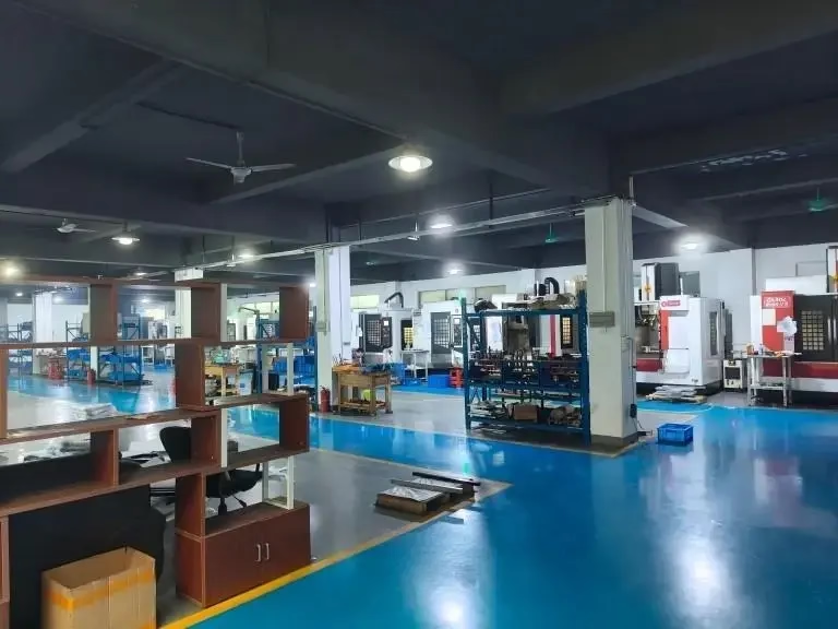
Yes, and most parts need it. We run 127 high-precision CNC machines across three plants, including 16 mill-turn centers, 16 simultaneous 5-axis machining centers, 12 four-axis mills and 27 three-axis machines.
For a part that is mostly turned with milled features, a mill-turn center keeps one datum and removes the second setup. For a part that is mostly prismatic, milling leads and turning handles the bores.
What is the largest part you can machine?
The maximum processing size is 4,000 mm, with a large travel of 4,000 × 400 × 150 mm. Medium travels cover 750 × 1,150 × 550 mm and 600 × 600 × 600 mm, and compact machines cover 500 × 500 × 450 mm and 500 × 310 × 200 mm.
Long parts are usually turned. Wide plates go on the larger gantry-style mills. If your envelope sits near a limit, send the drawing and we will confirm the machine before quoting.
How do you keep ±0.005 mm across a batch?
Machine, tool and thermal control together. We check first-article parts after a warm-up cycle, monitor in process, and compensate tool offsets as inserts wear. Inspections cover raw material, in-process checks and a final pass before shipment, and reports are available on request.
For long aluminium parts, measure at 20 °C. Aluminium 6061 grows about 23 μm per meter per °C, which is larger than the tolerance on a 1,000 mm part.
Which materials can you run?
Aluminium grades 6061, 6061-T6, 2024, 5052, 5083, 6063, 6082, 7075 and ADC12; stainless 303, 304, 316, 316L, 420, 430, 431, 440C and 17-4PH; steels 1018, 1045, 4130, 4140, 4340 and A36; copper and brass C101, C103, C110, C27400, C28000 and C36000.
Titanium TA1, TA2 and TC4, Inconel and magnesium AZ31B and AZ91D are also in regular rotation, along with ABS, PC, PMMA, POM, PA, PEEK, PP, HDPE and carbon fibre.
Do you have a minimum order quantity?
No minimum. We run from one prototype to 10,000+ part runs on the same process route, so the fixture and program you pay for at prototype stage carry into production.
Uploads are kept secure and confidential, and an NDA is available on request before you send files.
How fast can a quote and parts come back?
We return a quotation and a free DFM analysis within 12 hours. Production can start within 24 hours of approval, and parts typically ship in 3–5 days depending on geometry, finish and material.
If a feature in your drawing will not survive the first operation, we flag it in the DFM notes rather than discovering it on the machine.
Send a drawing, get a process route
Upload your files and we will return a quote, a DFM analysis and a recommended process route within 12 hours. No minimum order quantity, and NDA available on request.
12-hour quote100% inspectionNo MOQ
More process notes
We publish setup notes, tooling trials and inspection data from the factory floor.











