
CNC Milling Foundation
A working explanation of how a milling cut removes material, which machine configuration fits which part, and where the process stops being economical. Written for design and manufacturing engineers who need to judge a part before sending it out for quote.
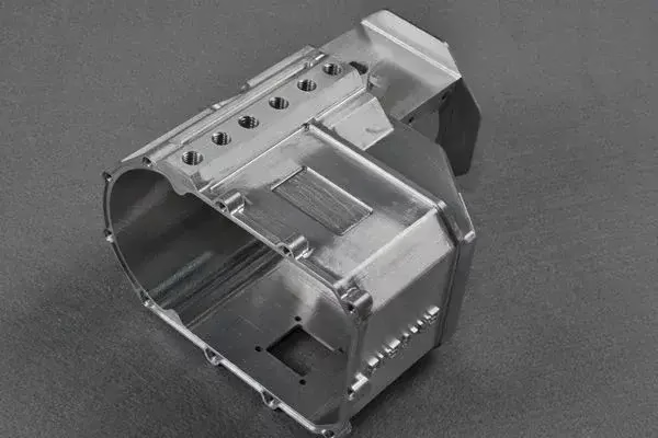
What actually happens at the cutting edge
A CNC milling foundation starts at the tool tip, not at the control. A multi-flute cutter rotates at a set spindle speed while the table feeds the workpiece into it. Each flute takes a chip of finite thickness. If the chip is too thin, the edge rubs instead of cutting, work-hardens the surface, and burns up the insert. If the chip is too thick, the tool deflects and the wall you just finished bows outward. The sweet spot sits between those two failures, and it is set by feed per tooth, not by spindle speed.
For aluminum, a 12 mm three-flute carbide cutter in 6061 runs well around 8,000 rpm and 0.10 mm per tooth. For 316 stainless, drop to roughly 0.05 mm per tooth and cut the surface speed by two thirds. These are starting points. The right number depends on the rigidity of the setup, the depth of cut, and how the part is held. A part that rings when you tap it will chatter no matter what feed you dial in.
Climb milling is the default for most work. The tooth enters at maximum chip thickness and exits at zero, which pushes the cutting force down into the table instead of lifting the part. Conventional milling still has a place on castings and forgings with a hard skin, because the edge enters under the skin rather than biting into it. On a clean billet, climb milling gives better surface finish and longer tool life.
CNC milling foundation: 3-axis, 4-axis, or 5-axis
The number of axes describes how many directions the tool can approach the work. A 3-axis mill moves in X, Y, and Z only. The tool always points straight down. This is the cheapest, most rigid, and fastest option, and it covers a large share of real parts: plates, brackets, housings with features on one face, and anything you can reach from above.
A 4-axis mill adds rotation around one axis, usually the X or the table. That single rotary move lets you cut several faces in one setup without re-fixturing. Shafts with flats, parts with pockets on two opposite sides, and cylindrical features with cross-holes all benefit. Every re-fixture costs setup time and adds stack-up error, so eliminating one is often worth the machine rate.
A 5-axis mill adds a second rotary axis, so the tool can tilt. This is what lets a cutter reach undercuts, blend a curved surface in one continuous pass, and drill a hole at an angle without a custom fixture. GreatLight runs 16 simultaneous 5-axis machining centers next to 27 three-axis machines and 12 four-axis mills, because the right answer changes part by part.
The trade is real. A 5-axis machine is slower to program, harder to fixture, and less rigid at the extreme of its rotary travel than a 3-axis machine of the same size. If your part can be cut from three directions, a 3-axis machine will usually hit tolerance faster and cheaper.
Tolerance, surface finish, and what they cost
On a drawing, ±0.005 mm is a general callout, not a promise that every dimension lands there. The dimensions that actually matter are the ones tied to function: a bearing bore, a mating face, a dowel hole. Machining every dimension to the tightest number on the sheet is a way to pay for accuracy you will never measure.
Surface finish follows the same logic. Ra 1.6–3.2 μm is a normal as-machined finish straight off the cutter. Ra 0.8–1.6 μm usually means a finer stepover or a finishing pass with a smaller tool. Ra 0.2–0.8 μm generally needs a separate operation, and on some materials it cannot be held by milling at all. Specify the finish only on the faces that seal, slide, or take a coating.
Material changes the finish you can reach. Aluminum 6061 and 7075 cut clean and hold Ra 0.8 μm without much fuss. 316 stainless work-hardens, so a dull tool will smear the surface and pull the finish out of spec. Titanium TC4 (Ti-6Al-4V) needs sharp edges, low surface speed, and plenty of coolant, or the cutter will fail before the part does.
Wall thickness is the quiet cost driver. A 0.5 mm wall in a 100 mm long pocket will deflect under cutting force. It can be machined, but it needs light radial passes and often a support or a sacrificial web. Tell the shop the wall is thin. The programmer will change the strategy, and the part will come off the machine straight.
Material behavior and workholding choices
Aluminum is the easy case. It cuts fast, conducts heat away from the edge, and tolerates aggressive parameters. Plastics like POM and PEEK are the opposite. They melt, they grab the tool, and they spring back after the cut. Use sharp single-flute cutters, high spindle speed, and air blast instead of flood coolant. PEEK especially will hold a burr that needs a secondary deburr pass.
Steels split into two groups. 1018 and 1045 are plain carbon and machine predictably. 4140 and 4340 are alloy steels that respond to heat treatment, so the sequence matters: rough machine, heat treat, then finish machine after the hardness is set. Cut them before heat treat and the part will move. Cut them after and you need carbide that can handle the hardness.
Workholding decides whether the tolerance is reachable. A vise is fine for a block. A thin plate needs a vacuum chuck or tabs, or it will bow when the vise releases. A part with features on five sides needs either a 5-axis setup or a soft jaw fixture machined in place. Every time the part is released and re-clamped, the datum shifts a little. Fewer setups means fewer chances to lose the number.
Confidentiality matters on defense and medical work. Uploads stay secure and confidential, and an NDA can be in place before files move. That is standard practice, not a special request.
Where milling stops making sense
Milling is subtractive. It removes material from a solid block, which means the cycle time scales with the volume you have to remove. A part that starts as a 4,000 mm frame and ends as a 200 g bracket wastes most of the stock. For high-volume parts with that shape, die casting or sheet metal will beat milling on unit cost once the tooling is amortized.
Deep, narrow features are the other wall. A pocket deeper than four times its width needs a long, slender tool, and slender tools deflect. You can reach 8:1 with a carbide tool and light passes, but the surface finish will suffer and the cycle time climbs. If the pocket is deeper than that, ask whether it can be a drilled hole, a cast feature, or two parts bolted together.
Sharp internal corners have a hard limit too. The cutter has a radius, so the smallest internal corner is the radius of the smallest tool that can reach it. A 0.5 mm corner needs a 1 mm cutter, which cannot go deep. Draw a corner radius that matches a standard tool and the part gets cheaper without losing function.
None of this means milling is the wrong choice. It means the foundation of the process is a set of trade-offs, and a part designed with those trade-offs in mind will quote lower and run better.
Which milling configuration fits the part
Match the geometry to the machine before you worry about the price.
| Part feature | Best fit | Why |
|---|---|---|
| Flat plate, pockets on one face | 3-axis | One setup, maximum rigidity, lowest cost |
| Flats and cross-holes on a shaft | 4-axis | Rotary index removes a second fixture |
| Undercut or angled hole | 5-axis | Tilting tool reaches past the overhang |
| Curved surface needing one blend | 5-axis | Tool stays normal to the surface |
| Deep pocket, 4:1 depth to width | 3-axis + long reach tool | Deflection matters more than axis count |
| Thin wall under 1 mm | 3-axis, light passes | 5-axis rotary force can distort the wall |
| Large frame, 4,000 mm long | Large-travel 3-axis | Gantry travel, no rotary needed |
The short version
If the part can be cut from three directions, use 3-axis. If it has features on four or five sides, or a curved surface that must blend in one pass, pay for 5-axis. Match the axis count to the geometry, not to the machine list.
Questions engineers ask
Can a 3-axis mill hold ±0.005 mm?
Yes, on a rigid setup with a controlled temperature and a sharp tool. The tolerance is achievable on a 3-axis machine when the features are reachable from one or two directions.
The limit is usually the fixture, not the machine. If the part moves when it is clamped, no axis count will save the dimension.
When is 5-axis worth the higher rate?
When it removes a fixture, reaches an undercut, or holds a curved surface in one continuous pass. Each of those saves setup time or avoids a stack-up error.
If none of those apply, a 3-axis machine with a good fixture will usually be faster and cheaper.
What surface finish comes standard?
As-machined is typically Ra 1.6–3.2 μm. A finishing pass gets to Ra 0.8–1.6 μm on most metals.
Ra 0.2–0.8 μm needs a separate operation and should only be called out on faces that need it.
How thin can a milled wall be?
Down to about 0.5 mm in aluminum with light passes and a support web. Below that, the wall deflects under cutting force and the part will not stay straight.
Tell the shop which walls are thin so the programmer can adjust the strategy before the first cut.
Does the part need to be heat treated before or after milling?
Rough machine first, heat treat, then finish machine. That order lets the part move during heat treat and still be brought to final size afterward.
Finishing before heat treat risks distortion that no re-cut can fix.
What file format do you need for a quote?
STEP or IGES for the solid, plus a 2D drawing with the tolerance and finish callouts. The drawing carries the information the model cannot.
If the part is still in development, send what exists. A quote and a DFM review come back within 12 hours.
Send the part. Get a real answer.
Upload a STEP file and a drawing. We review the geometry, flag the features that will cost you, and quote within 12 hours.
12-hour quoteFree DFM analysis100% inspection
More from the shop floor
We publish setup notes, tooling trials and inspection data from the factory floor.











