
Do You Really Understand Surface Finishing?
Surface finishing is not a cosmetic afterthought on a CNC part. It sets friction, corrosion life, sealing and how the part fits. This page explains what the Ra number on your drawing actually controls, where each process stops working, and how to choose one without over-specifying.
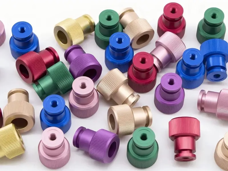
What surface finishing actually changes
Every machining operation leaves marks. An end mill sweeps across the face and leaves a scalloped path; a turning insert leaves a helical thread of feed marks; grinding leaves a finer but still directional pattern. Surface finishing is the set of operations that change the size, shape and distribution of those marks after the cutting is done.
The number that describes those marks is roughness, written Ra and measured in micrometres. Ra is the average deviation of the profile from its mean line over the measured length. A part machined with a sharp cutter at a light feed might read Ra 1.6–3.2 μm. A lapped or polished surface can reach Ra 0.2–0.8 μm, and that difference is roughly a factor of ten in peak height.
Ra alone does not tell you everything. Two surfaces can share the same Ra and behave differently: one has many shallow scratches, the other a few deep grooves. The deep grooves become crack starters under fatigue, and they leak past an O-ring while the shallow one seals. That is why a drawing that only says "smooth" is not enough information to quote or to inspect against.
If you want to understand surface finishing properly, stop treating it as a final cosmetic pass. It is a functional decision made at the same time as tolerance, material and heat treatment. Change the finish after the part is designed and you may change the fit, the seal, the coating adhesion and the inspection method all at once.
Where roughness comes from in the cut
The theoretical roughness left by a turning insert is set by feed rate and tool nose radius. The classic relationship is Ra ≈ f² / (32 × r), where f is feed per revolution and r is the nose radius. Feed the same insert at 0.2 mm/rev instead of 0.1 mm/rev and the theoretical Ra roughly quadruples. This is the single largest lever a programmer has over finish.
In milling the geometry is different but the logic is the same. Feed per tooth, cutter runout and the effective cutter diameter set the cusp height between passes. A 16 mm end mill with 0.05 mm runout will leave a visible step pattern no matter how slow the feed is, because one flute does most of the cutting. Runout beats parameter tuning every time.
Tool wear pushes roughness up over the life of a run. A new insert might hold Ra 1.0 μm, and the same insert at the end of its life may be at Ra 2.0 μm. On long runs we monitor surface with a portable profilometer and change inserts on a count, not on a hunch. The same applies to ball-nose cutters in 3D finishing, where a worn tip rounds the cusp and the surface goes dull before it goes rough.
Vibration and chatter leave a different signature: a periodic wave rather than random scratches. Often it appears as a spiral band on a turned face or a repeating pattern on a milled wall. No finishing process downstream will remove a chatter pattern cleanly, because the depth of the wave is usually 5–20 μm. Fix it at the machine: shorten the tool overhang, reduce radial engagement, add damping on thin walls.
How to understand surface finishing processes and their limits
Mechanical finishing covers bead blasting, tumbling, brushing and polishing. Bead blasting with glass beads at 0.1–0.3 MPa gives a uniform matte and hides tool marks, but it blurs sharp edges and can round a 0.5 mm chamfer into a soft radius. Tumbling is good for deburring many small parts at once; it will not hold a sharp corner. Polishing gets Ra 0.2–0.8 μm, but it is directional and slow, and it can round edges on the same scale.
Anodizing is an electrochemical conversion of the aluminium surface itself, not a coating laid on top. Clear and colour anodizing grows a layer typically 5–25 μm thick. That layer builds outward and inward roughly equally, so a tight bore grows smaller and a tight shaft grows larger. Hardcoat anodizing is thicker and harder, and it will close a press-fit hole. If you need an anodized bore at ±0.005 mm, machine the bore undersize and let us know before the parts go to the line.
Plating processes add metal: electroless nickel, zinc, silver and gold. Electroless nickel is the common choice for wear resistance and uniform coverage on complex geometry, but a 25 μm layer changes a mating dimension by 50 μm across a diameter. Zinc plating is decorative and sacrificial; it will not survive heavy sliding contact. Silver and gold are for conductivity and contact resistance, not for wear.
Powder coating and black oxide are the two ends of the scale. Powder coating builds 60–120 μm and covers everything, so mask threads, bores and grounding points. Black oxide converts the surface in place and adds almost no thickness, which makes it the right call when dimensions cannot move. Laser marking sits on top of any of these and needs a character height of at least 1.5 mm to stay legible after the finish.
Matching the finish to the function
Ask what the surface has to do. Sliding contact under load needs low Ra and some way to hold lubricant, so a hard, fine surface works better than a mirror. A sealing face needs a controlled roughness, not the smoothest surface possible: an O-ring seal often works best at Ra 0.8–1.6 μm, because a polished face gives the elastomer nothing to bite into and it can slip. Optical and vacuum surfaces are the opposite case and may need Ra below 0.4 μm.
Corrosion life usually comes from the coating, not from the Ra. Anodizing and plating do the work. But a rough surface under a thin coating gives pinholes and salt-spray failures, so if the service environment is aggressive, specify the base finish as well. A Ra 1.6–3.2 μm base under 25 μm of electroless nickel is a reasonable balance; an as-cast or heavily blasted base under 5 μm of plating is not.
Fits and assembly are where most surface finishing mistakes show up. A 30 μm powder coat on a bracket that slides into a slot will not fit. A hardcoat anodized thread will not accept its mating screw without chasing. We ask for the mating parts and the assembly sequence before we quote a finish, because masking and pre-machining allowances have to be planned before cutting starts.
Cost and lead time move with the process, not with the Ra number alone. Bead blasting and tumbling are the cheapest and fastest. Anodizing, plating and powder coating add a batch step with its own queue. Fine polishing is manual and the most expensive per part. If a drawing calls for Ra 0.2 μm across a large area, check whether the function really needs it or whether Ra 0.8–1.6 μm would do.
Measuring and specifying finish on a drawing
Ra is measured with a stylus profilometer over a cutoff length, usually 0.8 mm for machined surfaces. The cutoff matters. Measure a bead-blasted surface with a 0.8 mm cutoff and you get one number; measure the same surface with a 2.5 mm cutoff and you get a different, usually higher, number. State the cutoff and the measurement direction on the drawing, because a turned surface reads differently along the axis than around the circumference.
For most machined parts, a visual and tactile check plus a profilometer reading on a sample is enough. For sealing faces, bearing bores and medical or aerospace surfaces, we measure on the actual part and keep the record. GreatLight inspects 100% of parts before shipment, covering raw material check, in-process monitoring and final inspection, with reports on request.
On the drawing, use the standard surface texture symbol and put the Ra value with the process. "Ra 0.8 μm, turned" is more useful than "Ra 0.8 μm" alone, because it tells the shop which operation carries the requirement. Add a note if the finish applies to a specific face only. Blanket finish callouts across a whole part often force polishing on faces that never needed it and raise the price for no reason.
Surface finishing processes at a glance
Typical values for aluminium, stainless and steel parts. Actual results depend on geometry, masking and base finish.
| Process | Typical Ra | Thickness change | Best fit |
|---|---|---|---|
| As machined | Ra 1.6–3.2 μm | None | Non-critical brackets, internal parts |
| Bead blasting | Ra 1.6–3.2 μm | None | Uniform matte, hides tool marks |
| Tumbling / brushing | Ra 0.8–1.6 μm | None | Deburring small parts, soft sheen |
| Polishing | Ra 0.2–0.8 μm | None | Optical, sealing, low-friction faces |
| Anodizing (clear / colour) | Follows base Ra | 5–25 μm build | Wear and corrosion on aluminium |
| Hardcoat anodizing | Follows base Ra | 25–50 μm build | Sliding wear, abrasive contact |
| Electroless nickel | Follows base Ra | 10–25 μm build | Uniform wear and corrosion layer |
| Powder coating | Follows base Ra | 60–120 μm build | Exterior frames, colour, impact |
| Black oxide | Follows base Ra | Under 2 μm | Dimensional stability, light corrosion |
The call we would make
If the surface carries load, seals or mates, specify the finish and the process together and plan masking and pre-machining before cutting starts. If it is cosmetic or internal, leave it as machined and save the cost.
Common questions about surface finishing
Does a smoother surface always last longer?
No. A mirror surface can be worse for a sliding contact because it cannot hold lubricant, and it can be worse for an elastomer seal because the rubber has nothing to grip. The right roughness depends on the contact type.
For wear under load, a hard surface at Ra 0.8–1.6 μm with a crosshatch or lapped pattern usually outperforms a polished face at Ra 0.2 μm.
Will anodizing change my dimensions?
Yes. Anodizing grows a layer that builds both outward and inward, so an anodized bore gets smaller and an anodized shaft gets larger. Clear and colour anodizing typically build 5–25 μm; hardcoat builds more.
If a bore must hold ±0.005 mm after anodizing, tell us before machining and we will leave the allowance in the cut.
Can I call out Ra 0.4 μm on the whole part?
You can, but it will cost more and may not help. Fine polishing is manual and slow, and blanketing a whole part forces the operation onto faces that never touch anything.
Put the tight Ra only on the functional faces. Leave the rest as machined at Ra 1.6–3.2 μm.
Which finish is best for stainless steel?
Stainless does not anodize, so the mechanical options and plating are what remain. Bead blasting, tumbling, brushing and polishing all work, and electroless nickel adds wear resistance where the base metal would gall.
For food, medical or cleanroom parts we often leave a passivated machined or blasted surface rather than adding a coating.
How do I check the finish on incoming parts?
Use a portable stylus profilometer on a sample and compare against the drawing value with the same cutoff length the drawing specifies. Do not compare readings taken with different cutoffs.
For critical faces, ask for the inspection record from the finishing batch. We keep measurement records and can supply them with the shipment on request.
Does surface finishing add lead time?
Mechanical finishes like blasting and tumbling usually run alongside machining. Anodizing, plating and powder coating are batch steps with their own queue and can add days.
Tell us the finish at the quote stage. Parts ship in 3–5 days for standard work when the finish is planned in from the start.
Send us the drawing and the function
We quote in 12 hours with a free DFM review, and we will tell you if your finish callout is doing more than the part needs.
12-hour quote100% inspectionNo minimum order quantity
More CNC shop knowledge
We publish setup notes, tooling trials and inspection data from the factory floor.











