
G00 CNC Mastery: 7 Essential Fixes for Faster, Safer Rapids
Rapid moves are the cheapest air time in a cycle and the easiest place to crash a spindle. This guide is for programmers and setup engineers who need to trace a G00 problem to its root cause. Read it and you can tell whether a symptom comes from the clearance plane, the path geometry, the fixture, or the post processor.
In this article
- 1
- 2
- 3
- 4
- 5
- 6
- 7
Rapid move symptoms, causes, and fixes
Find the symptom you are seeing, then work the cause and the fix in the same row.
| Symptom | Likely cause | What to do |
|---|---|---|
| Cycle time drifts up, no crashes | Global Z retract set too high | Set clearance 1–3 mm above the tallest feature |
| Tool clips a clamp on the return path | Rapid path crosses fixture geometry | Model clamps in CAM and re-simulate the full path |
| Alarm or stall mid-rapid | Axis at rapid rate before the servo settles | Lower rapid rate for the last 5 mm, check drive tuning |
| Rapid stops short of the target | Work offset or fixture shift | Re-probe the datum and reset the work offset |
| Scrap on the first part of a run | Leftover stock on the rapid entry path | Cut an air-pass first part or add a stock check |
| Same program, different times | Two machines have different rapid rates | Match parameter sets or post per machine model |
| Short rapids cost more than they save | Thousands of tiny G00 moves | Merge moves or hold position without retract |
| Rapid goes through the part wall | CAM retract plane below the wall top | Raise retract above the highest stock surface |
Fix the path before you touch the rapid rate
Most rapid problems are clearance, geometry, or fixture issues, not a slow machine. Set the clearance from the tallest feature, simulate the holder, run an air pass, then re-time the cycle. If you are still losing time, send us the drawing and the cycle data and we will review the process plan.
What G00 actually does on a real machine
G00 tells the control to move at the machine's rapid rate. It does not tell the control how to get there in a straight line unless you are in G00 with linear interpolation active on that control, and it does not guarantee the axes arrive together. On many mills each axis runs at its own rapid rate, so the tool path is a stepped diagonal, not the clean line you drew in CAM. That gap between drawing and motion is where most rapid problems start.
Rapid rate itself is a machine parameter, not a program value. A 40-taper mill might rapid at 30 m/min in X and Y while Z runs slower. A large gantry machine may rapid at 20 m/min but take longer to accelerate. If you move the same program to a second machine, the path is the same on paper but the timing and the corner rounding are not.
This matters because the clearance you set in CAM is a physical distance, and the machine's acceleration behavior decides how much that distance is actually respected. A control that starts decelerating late will overshoot the target slightly before it settles. On a rapid into a deep pocket, that overshoot is the difference between an air move and a gouge.
- 1Rapid rate is a parameterRead it from the machine manual, do not assume it from the CAM default.
- 2Axes do not always arrive togetherNon-interpolated rapid produces a stepped path in 3D.
- 3Acceleration matters as much as top speedShort rapids never reach the rated rate.
Clearance plane errors and how to set them
The most common rapid fault is a single global clearance height used for the whole program. It is set once in the operation and never revisited. On a flat plate with a few holes, that is fine. On a part with a deep pocket next to a tall boss, the same height is either too low over the boss or too high over the pocket.
Work from the geometry, not from habit. Measure the tallest feature the tool must clear, add the tool holder radius, then add 1 to 3 mm. That is your retract height for that operation. For a side wall at 40 mm, a clearance of 42 mm is enough. A global 50 mm retract over a shallow pocket wastes travel on every single hole.
Check the clearance against the holder, not just the cutter. A long reach tool with a 20 mm shank needs more room than a stub cutter. If the holder can touch a clamp on the retract, the program is wrong even when the cutter path looks clean. Model the holder in CAM and let the simulation show the collision.
On parts with several features on the same face, a fixed height is rarely optimal. Use a separate clearance per operation or per feature group. The extra CAM setup time pays back within a few parts on any cycle with more than a handful of holes.
- 1Measure the tallest feature firstAdd holder radius plus 1–3 mm for the retract plane.
- 2Model the holderA clean cutter path can still crash the shank.
- 3Set clearance per feature groupOne global height is either slow or unsafe.
Rapid path geometry in three dimensions
Programmers who think in XY only leave Z at the safe plane for the whole move. The tool rises, travels across, then drops. That is two moves where one diagonal move would do. On a housing with twenty features, those extra moves add up to real cycle time without any cutting benefit.
A diagonal rapid is faster when the control interpolates the rapid. Instead of retracting, crossing, and plunging, the tool leaves at an angle and arrives at the next start point directly. The catch is that the diagonal must clear every feature between the two points. Simulate it, then verify the lowest point on the diagonal against the stock model.
Do not diagonal-rapid over a fixture or a clamp. The straight-line distance looks shorter on the screen, but the clamp height is what decides whether the move is safe. If the diagonal passes over a clamp, keep the move orthogonal and accept the extra seconds.
For deep pockets, a diagonal entry from the clearance plane to the next cut level avoids a full retract between levels. Use it when the wall geometry allows, and keep a 1 to 2 mm margin from the wall. This is the kind of change that cuts non-cutting time without touching a single feed rate.
- 1Diagonal rapids save timeOne interpolated move replaces retract, cross, and plunge.
- 2Verify the lowest pointCheck the diagonal against the stock model, not the screen.
- 3Never diagonal over a clampKeep the orthogonal move when fixture geometry is in the way.
Predicting the invisible rapid collision
A rapid collision usually has nothing to do with the cutter path you drew. It happens because the stock in the machine is not the stock in the model. A casting with 3 mm of extra material on one face, a block that was sawn 2 mm oversize, or a fixture that was repositioned between setup sheets will all put solid material where the CAM file shows air.
The fix is a first-part air pass. Run the program with the tool offset raised by 5 to 10 mm and the feed override at a low setting. Watch where the rapid moves go. If the tool passes through a region that should be clear, stop and compare the actual stock to the model. This takes a few minutes and catches the class of crash that simulation cannot see.
Leftover stock from a previous operation is another source. A roughing pass that leaves a 0.5 mm skin on a wall is invisible in the CAM tree until the finishing operation rapids into it. Check the in-process stock model after each operation, not just the final part.
Fixture changes between the first and second setup are the third common cause. If a clamp was moved 10 mm to clear a drill, the rapid path from the old setup no longer clears it. Keep a fixture layout drawing and check it against the program before the run starts.
- 1Air pass firstRaise the offset 5–10 mm and watch the rapids.
- 2Check in-process stockA thin roughing skin is still solid material.
- 3Verify fixture layoutA clamp moved 10 mm can invalidate the whole path.
Small rapids, machine behavior, and the post processor
A rapid that lasts 0.1 seconds never reaches the machine's rated rapid rate. It accelerates, may not reach full speed, then decelerates. On a cycle with hundreds of these micro-moves, the control spends most of its time in acceleration. The fix is not to speed up the rapid, it is to remove the move. If the next operation starts at the same point, hold position instead of retracting.
Machine personality is real. Two identical mills from the same builder can have different acceleration parameters, different rapid rates on Z, and different corner rounding behavior. A post processor tuned for one machine will produce a program that runs well there and poorly on the other. Keep a separate post per machine model and verify the rapid parameters against the machine manual.
The post processor also decides how G00 is written. Some posts output a single G00 line with all three axes, which lets the control interpolate. Others output axis-by-axis moves, which forces a stepped path. Check the output for a simple three-axis move and see which form you get. If it is axis-by-axis, that is a post setting, not a machine limit.
Finally, check whether the control has a rapid override or a rapid rate select. Many operators run at a reduced rapid rate during prove-out and forget to restore it. A cycle that looks slow in production may simply be running at 50 percent rapid override. Confirm the override before you rewrite the program.
- 1Micro-rapids waste timeShort moves never reach the rated rapid rate.
- 2One post per machineAcceleration and Z rapid rates differ between units.
- 3Check the overrideA 50 percent rapid override looks like a slow program.
Step-by-step rapid troubleshooting
Work these in order. Stop as soon as the symptom disappears.
- 1Confirm the rapid override and feed hold stateCheck the control panel before touching the program. A rapid override at 25 to 50 percent makes a healthy program look slow. Restore it to 100 percent and re-time the cycle.
- 2Read the actual rapid parametersPull the rapid rate for each axis from the machine manual or parameter screen. Write the X, Y, and Z values on the setup sheet. Do not assume the CAM default matches the machine.
- 3Measure the tallest feature and reset clearanceAdd the tool holder radius, then 1 to 3 mm. Set the retract plane from the measurement, not from the previous job. Re-run the simulation with the holder modeled.
- 4Compare the actual stock to the CAM stockMeasure the block or casting at three points. If it is more than 1 mm oversize, update the stock model before you trust the rapid paths.
- 5Run a first-part air passRaise the tool offset by 5 to 10 mm, slow the feed override, and watch every rapid. Stop on any move that passes within 2 mm of a clamp or the stock.
- 6Look for micro-rapids in the cycleScan the program for G00 moves shorter than 5 mm. Merge them or hold position. This is usually the largest single time saving on a drilling-heavy cycle.
- 7Check the post output formConfirm the post writes a single G00 line with all three axes. If it writes axis-by-axis moves, change the post setting and re-post the program.
- 8Re-time and record the resultRun the optimized cycle three times and record the times. Keep the numbers with the setup sheet so the next programmer knows what the machine actually does.
Rapid move questions we get from engineers
Why does the same program run faster on one machine than another?
Rapid rate and acceleration are machine parameters, not program values. Two machines with the same control can have different Z rapid rates, different acceleration ramps, and different corner rounding behavior.
Check the parameter set on both machines and compare the rapid rates per axis. If they differ, keep a separate post processor per machine model so the program matches the hardware.
How high should the clearance plane be?
Measure the tallest feature the tool must clear, add the tool holder radius, then add 1 to 3 mm. That is the working clearance for that operation.
A single global height across a part with both shallow pockets and tall bosses is either slow or unsafe. Set clearance per feature group instead.
Can I use G00 for a diagonal move into a pocket?
Yes, when the control interpolates the rapid and the diagonal clears every feature between the two points. Verify the lowest point of the diagonal against the stock model, not just the screen view.
Do not diagonal-rapid over a clamp or any fixture geometry. Keep that move orthogonal and accept the extra seconds.
Why did the tool crash on a rapid when the simulation was clean?
The simulation used the CAM stock, and the machine held something different. An oversize block, a casting with extra material on one face, or a clamp moved between setups will all put solid material where the model shows air.
Run a first-part air pass with the offset raised 5 to 10 mm and watch the rapids. That catches what simulation cannot see.
Is a higher rapid rate always better for cycle time?
No. Short rapids never reach the rated rate, so raising the top speed changes nothing on a cycle made of 0.1 second moves. The gain comes from removing the move, not from making it faster.
Merge short rapids, hold position when the next operation starts at the same point, and reset the clearance plane before you touch the rapid rate parameter.
What tolerance and finish can GreatLight hold on rapid-heavy cycles?
We machine to ±0.005 mm and can hold Ra 0.8–1.6 μm on standard finishes, with Ra 0.2–0.8 μm available when the drawing calls for it. Rapid optimization is part of the process planning, not a separate step.
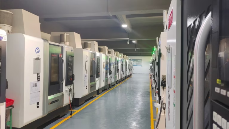
We run 127 high-precision CNC machines across three wholly-owned plants, including 16 simultaneous 5-axis centers and a 4,000 mm maximum processing size.
Send us the part that keeps crashing on rapids
Upload your drawing and the current program. We will quote within 12 hours and include a free DFM review of the rapid and clearance strategy.
12-hour quoteFree DFM analysisNo minimum order quantityNDA on request
More process notes from the shop floor
We publish setup notes, tooling trials and inspection data from the factory floor.











