
CNC milling mastery: what changes when the part gets giant
CNC milling mastery on giant parts is not a bigger version of small-part work. Thermal drift, fixture stiffness and 5-axis reach all behave differently once a part passes roughly 1 m. This page explains the mechanism, the limits, and how to judge whether a shop can hold your size.
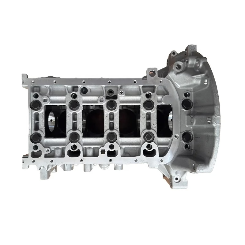
Why CNC milling mastery changes with part size
A 4,000 mm part is not a 100 mm part scaled up. Every error source grows with the workpiece, but the machine envelope does not grow at the same rate. A VMC with 4,000 × 400 × 150 mm travel has a long, slender column relative to its reach. Push a face mill across the far end of that table and the tool deflects under load. The same cutter at the center of the table cuts clean.
Heat is the second shift. Cutting 7075 or 17-4PH for two hours puts several kilowatts into the chips and the coolant. On a small part, the body acts as a heat sink and stabilizes. On a 3 m casting, the far end may still be at ambient while the machined pocket is 6 °C warmer. Steel grows about 11 μm per meter per °C, so a 6 °C gradient across 3 m moves the far end roughly 0.2 mm.
That number is larger than most of the tolerances on the drawing. It is why a shop that holds ±0.005 mm on a 50 mm bracket cannot promise the same figure on a 3 m weldment without a plan for heat.
Geometry adds a third effect. A 4,000 mm travel machine with 400 mm in Y is built for long, narrow parts. Wide plates need a different platform. Matching the part envelope to the right machine matters more than the tolerance printed on the brochure.
- 1Stiffness scales downLong travels mean more overhang at the tool tip.
- 2Heat scales upA 3 m steel part moves about 0.2 mm per 6 °C gradient.
- 3Envelope shape matters4,000 × 400 × 150 mm suits long parts, not wide plates.
What simultaneous 5-axis adds on giant work
A 3-axis machine reaches a face by moving the table under the spindle. On a long part, that means repositioning the workpiece, and every reposition adds setup error. A simultaneous 5-axis center tilts the head or the rotary table instead, so five faces can be cut in one setup. Fewer setups means fewer datum transfers, and datum transfer is where large-part accuracy usually dies.
The rotary table is the practical limit. On the machines we run, the largest rotary table is Ø400 mm. A part that fits inside that circle can be indexed and cut from many directions. A part longer than the table can still be machined, but the ends have to be reached by moving the gantry or by repositioning the fixture.
Tilt also changes the cutting geometry. A bull-nose cutter held at 45° to a wall reaches into pockets that a straight tool cannot touch, and it leaves a different scallop pattern. Programmers have to model that pattern. If they do not, the finishing pass leaves marks that hand polishing has to remove later.
Not every giant part benefits. A flat plate with drilled holes and a milled step is faster on a 3-axis machine with a large table. Five-axis pays off when the part has angled faces, deep pockets, or features on more than three sides.
- 1One setup, five facesCuts datum transfers on long parts.
- 2Ø400 mm rotary limitLarger parts need gantry travel or fixture moves.
- 3Tool tilt changes finishScallop pattern must be programmed, not discovered.
Fixturing is where giant parts are won or lost
A 500 kg part sitting on three points will sag between them. Clamp it down and you push that sag into the part. Release the clamps after machining and the part springs back, and the flat face you just cut is no longer flat. The amount depends on wall thickness, rib layout and how the casting was stress-relieved.
The fix is not more clamps. It is a support plan that matches the part's own stiffness. Long parts are usually supported on a full bed of blocks or on a sub-plate, with clamps placed over the stiffest ribs rather than at the ends. On thin-wall housings, we sometimes machine a roughing pass, release, let the part rest, then take a light finishing pass.
Residual stress is the hidden variable. A weldment that was never normalized will move after the first heavy cut, no matter how good the fixture is. For parts that must hold ±0.005 mm across 2 m, the blank usually needs stress relief before it reaches the machine.
This is a decision the shop should raise before quoting, not after the first article fails. If the drawing calls for a tight flatness on an unstressed weldment, that is a process problem, not a machining problem.
- 1Clamping pushes sag inRelease after cutting and the face springs back.
- 2Rough, release, finishA rest between passes lets the part settle.
- 3Stress relief firstUnnormalized weldments move after heavy cuts.
What ±0.005 mm means on a 4,000 mm part
The ±0.005 mm figure in our capability list is a machine-and-process capability, measured on parts where the geometry and the material allow it. It is not a blanket promise for every size. On a 3 m aluminum extrusion, temperature alone can eat that budget before the cutter touches metal.
The useful question is not what the shop's best number is. It is what the shop will guarantee on your specific part, at your specific size, with your material. A shop that answers that question with a number and a reason is worth more than one that quotes the same tolerance for everything.
Inspection has to match the size too. A CMM with a 500 mm envelope cannot measure a 3 m part in one setup, so the shop needs either a larger CMM or a portable arm, and it needs to say which. Reports on request are standard for us, but the method behind the report is what tells you whether the number is real.
Surface finish follows the same logic. Ra 0.8–1.6 μm is achievable on most of our aluminum and stainless work. On a deep pocket in 17-4PH, tool reach limits the finishing strategy, and the achievable finish drops. Ask for the finish at the feature, not for the part as a whole.
- 1Tolerance is per featureA flat plate and a deep pocket do not share a number.
- 2Ask for the methodWhich CMM or arm, and how the part is set.
- 3Finish at the featureReach limits the achievable Ra inside pockets.
How we sequence a giant CNC milling job
- 1Review the model and the blankCheck wall thickness, rib layout and how the blank will be held. Flag any feature that needs a 5-axis setup.
- 2Decide the datum schemePick datums that survive every setup. On long parts, one datum per end usually beats one central datum.
- 3Stress relief if neededFor weldments and heavy castings, normalize before machining. This is scheduled, not improvised.
- 4Rough with stock leftLeave 0.3–0.5 mm on faces that will be finished after the part has settled.
- 5Rest and re-checkLet the part come back to room temperature. Re-measure the datums before the finishing pass.
- 6Finish and inspectLight finishing cuts, then 100% inspection before shipment, with reports on request.
Which machine platform fits which giant part
Match the part envelope and feature set to the platform before comparing tolerances.
| Part type | Best platform | Why |
|---|---|---|
| Long base, 2–4 m, 3 faces | 3-axis gantry | Long travel, few setups needed |
| Angled faces, deep pockets | Simultaneous 5-axis | Five faces in one setup |
| Round housing under Ø400 mm | 5-axis with rotary table | Indexed access from all sides |
| Wide plate over 1 m in Y | Large 3-axis VMC | Gantry Y travel is too narrow |
| Thin-wall weldment | 3-axis with rough/finish split | Stress must release between passes |
| Prototype, one off | 3-axis or 5-axis, no fixture | Setup cost dominates the run |
The short version
If your part is long, flat and mostly 3-sided, a large 3-axis platform is faster and cheaper. Choose simultaneous 5-axis when the part has angled faces or features on more than three sides, and accept the fixture and stress-relief work that comes with it.
Questions engineers ask about giant parts
What is the largest part you can machine?
Our largest travel is 4,000 × 400 × 150 mm. That platform suits long, narrow parts. We also run 750 × 1,150 × 550 mm and 600 × 600 × 600 mm machines for wider work, plus a Ø400 mm rotary table for indexed 5-axis cuts.
Can you hold ±0.005 mm on a 3 m part?
Sometimes, but it depends on material, geometry and how the blank was prepared. On aluminum, thermal growth alone can consume that budget across 3 m. We tell you what we can hold on your specific part before we start, not after.
Do you machine weldments?
Yes. Weldments usually need stress relief before machining, or the part will move after the first heavy cut. If the drawing calls for tight flatness on an unnormalized weldment, we raise that at quoting.
How do you inspect a part that big?
With equipment sized for the job. A small CMM cannot cover a 3 m part in one setup, so we use either a larger CMM or a portable arm, and we state which method produced the report. Inspection reports are available on request.
What is the minimum order quantity?
There is no minimum. We run from one prototype up to 10,000+ part runs. For a giant part, the first article usually doubles as the fixture validation.
How do you keep our drawings confidential?
Uploads are secure and confidential. We can sign an NDA on request before any file reaches the shop floor.
Send us the part and the drawing
Quotation and free DFM analysis within 12 hours, with a straight answer on what tolerance your part can actually hold.
12-hour quote100% inspectionNDA on request
Follow GreatLight
We publish setup notes, tooling trials and inspection data from the factory floor.











