
How CNC Machine Tools Are Manufactured
This guide walks through how CNC machine tools are manufactured, from casting design and stress relief to scraping, geometric alignment and laser verification. It is written for engineers and buyers who need to judge machine build quality, quote a build, or audit a supplier. By the end you will know which steps decide final accuracy and which ones are mostly cosmetic.
In this article
- 1
- 2
- 3
- 4
- 5
- 6
- 7
- 8
Key takeaways
How CNC machine tools are manufactured: design and casting
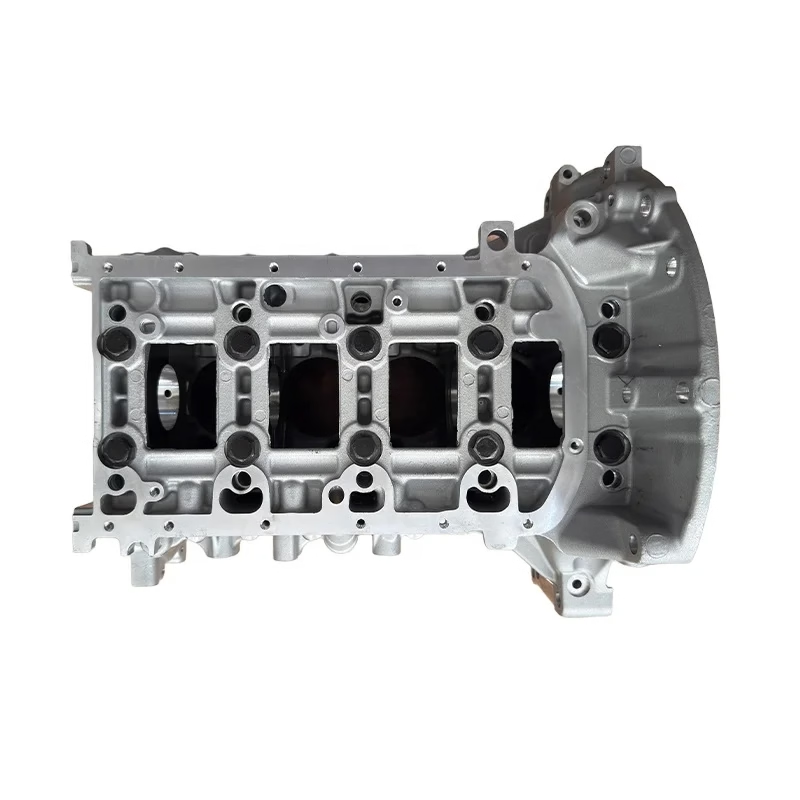
Every build starts with a specification, not a CAD model. The end user defines workpiece envelope, spindle power, axis count and target tolerance. That envelope decides whether the bed is a 4,000 mm cast iron structure or a 600 × 600 × 600 mm fabricated frame. Get this wrong and no amount of scraping will fix it later.
Design engineers then model the load path. Ribs are placed where cutting force enters the structure, usually under the spindle nose and at the column-to-base joint. A common error is adding wall thickness instead of adding ribs. Thick walls raise mass and cost without improving dynamic stiffness much. Modal analysis at this stage shows where the frame will ring.
Castings are poured, then stress relieved before any machining. Rough machining removes the skin, and a second stress relief follows. Without that second cycle, the casting moves 20–40 μm over the first year as internal stress releases. This is why a cheap frame is accurate on day one and out of square by month six.
Fabricated steel frames behave differently. They are welded, normalized, then machined in one setup where possible. Welding distortion is predictable but larger than casting shrinkage, so extra stock of 2–3 mm on critical faces is normal. For very large travels, a welded frame is often the only practical route.
- 1Define the envelope firstWorkpiece size, spindle power and axis count drive every later decision.
- 2Ribs over wall thicknessLoad path geometry controls stiffness more than raw mass.
- 3Two stress relief cyclesRough machine, relieve again, then finish machine.
Thermal design and spindle build
Heat is the quiet enemy of machine accuracy. The spindle, ball screws, motors and linear guides all generate heat during a shift. Left alone, a 1.5 m column can grow 20 μm or more. Good machines compensate by design, not by software alone.
Coolant channels are routed symmetrically around the spindle housing and screw nuts. Symmetry matters more than flow rate. An asymmetric jacket pushes the housing to one side as it warms, which shows up as taper in bores after two hours of cutting.
Spindle assembly is done in a temperature-controlled room, typically held at 20 ±1 °C. Bearings are matched in pairs, preloaded to a specified value, and the rotor is balanced to ISO 1940 grade G1 or better. Runout at the taper is checked with a test bar and a 0.001 mm indicator. Values above 5 μm usually mean a damaged or wrongly seated bearing.
After assembly, the spindle runs a warm-up cycle and the thermal map is recorded. The machine controller stores compensation values based on that map. If you buy a machine and never repeat this cycle in your own shop, expect the first two hours of every morning to cut differently from the afternoon.
- 1Symmetrical coolingRoute coolant evenly to avoid one-sided growth.
- 2Matched bearing pairsPreload and balance decide taper runout, target under 5 μm.
- 3Repeat the warm-upThermal compensation values are only valid for the environment they were measured in.
Machining, scraping and geometric alignment
The structural parts are finish machined to tight flatness, often 5–10 μm over a 1 m face. Milling and grinding get the geometry close, but they leave tool marks and small waviness. On sliding surfaces, that waviness causes stick-slip and poor surface finish on the workpiece.
Hand scraping removes the last layer and creates bearing points. A scraper works the surface until a reference plate shows 20–25 contact points per square inch on a precision slide, or 10–15 points on a general-purpose one. Scraping also lets the fitter steer the geometry. You cannot steer a ground surface; you can steer a scraped one.
Alignment is then done in sequence. First the bed is leveled to 0.02 mm/m. Then the column is squared to the bed, then the spindle is squared to the table, then the axes are checked for straightness and parallelism. Each step references the previous one, so an error early on multiplies.
The whole alignment is repeated after a 4-hour warm-up. Cold geometry and hot geometry differ, and the final acceptance values come from the hot condition. A machine that measures perfectly cold but drifts after warm-up will fail ISO 230-2 checks in the customer's plant.
- 1Scrape for contact points20–25 points per square inch on precision slides.
- 2Align in sequenceBed, column, spindle, axes. Never skip a reference step.
- 3Check hot and coldFinal values come from the warmed-up condition.
Electrical integration, drives and the control loop
Electrical build usually runs in parallel with mechanical assembly, then joins it at the end. Cabinets are wired to the machine's own drawing set, with each cable numbered at both ends. This sounds basic. It is also where most field faults originate, because a mislabeled encoder cable can take days to trace.
Servo drives are tuned after the mechanics are aligned. The tuning sequence is gain first, then feed-forward, then notch filters to kill resonance from the frame. If the frame is soft, the filters end up doing too much work and the machine feels sluggish in corners. On a rigid frame, tuning is quick and the axes stay stable at higher gains.
Encoder feedback is verified against a laser interferometer, not against the drive's own display. The drive display shows commanded position. The laser shows actual position. The difference between them is the real error, and it is the number that goes into the acceptance report.
Finally the tool changer, coolant system, chip conveyor and safety interlocks are tested. A tool change should complete without shock and repeat to within 0.01 mm at the spindle taper. Any hesitation here is usually a cam or a pneumatic pressure problem, not a control problem.
- 1Number every cableLabel both ends; field faults are easier to trace.
- 2Tune after alignmentMechanics first, then gain, feed-forward and notch filters.
- 3Verify with a laserDrive display is commanded position, not actual position.
Final verification and what the acceptance report should show
The last stage is measurement, and it is the stage buyers should read most carefully. A machine tool is verified against ISO 230-2 for positioning accuracy and repeatability, and against ISO 10791 for machining center geometry. Ask for the raw data, not a summary page.
Positioning error is reported bidirectionally. A machine that approaches a point from the left and from the right will land in slightly different places because of backlash and screw pitch error. Reporting only one direction hides that. The bidirectional value is the one that matters for interpolated work.
Squareness between axes is checked with a granite square and an indicator, or with a laser and a straightness optic. Typical acceptance for a general machining center is 0.01 mm/m or better. For a precision machine, 0.005 mm/m is realistic. Anything looser will show up as taper in bores and mismatch at corners.
Roundness and surface finish are proven by a test cut, not by a spec sheet. A common test is a circular interpolation cut in aluminum, measured on a roundness tester. Deviations show servo mismatch, backlash, or a sticking slide. This is the cut that separates a well-built machine from a well-painted one.
- 1Demand raw ISO 230-2 dataBidirectional values, not a single best-direction number.
- 2Check squareness with a granite square0.01 mm/m general, 0.005 mm/m precision.
- 3Cut a test circleRoundness and finish reveal servo and slide problems.
Step by step: building and checking a machine tool
- 1Fix the specificationWrite down workpiece envelope, spindle power, axis count and target tolerance. This document drives every later choice. Do not start CAD until it is signed off.
- 2Design the load pathPlace ribs under the spindle nose and at the column joint. Run modal analysis and push the first natural frequency above 40 Hz for general work.
- 3Cast, relieve, rough machineStress relieve after casting, rough machine leaving 2–3 mm stock, then relieve again before finishing.
- 4Finish machine and scrapeMachine critical faces to 5–10 μm flatness over 1 m, then scrape slides to 20–25 contact points per square inch.
- 5Align in sequenceLevel the bed to 0.02 mm/m, square the column, square the spindle to the table, then check axis straightness and parallelism.
- 6Assemble and tune the spindleBuild in a 20 ±1 °C room, preload matched bearings, balance to ISO 1940 G1, and check taper runout below 5 μm.
- 7Tune drives and verify with a laserSet gain, add feed-forward, apply notch filters. Confirm encoder feedback against an interferometer, not the drive display.
- 8Run warm-up and acceptWarm up 4 hours, repeat alignment, then record ISO 230-2 bidirectional positioning data and a roundness test cut.
Which build detail tells you what
Use this table when auditing a supplier or comparing two builds.
| Build detail | What it controls | Watch for |
|---|---|---|
| Stress relief cycles | Long-term dimensional stability | Only one cycle listed in the process sheet |
| Rib layout and wall thickness | Dynamic stiffness and chatter | Thicker walls quoted as the main selling point |
| Coolant channel symmetry | Thermal drift during a shift | Asymmetric jackets, no thermal map supplied |
| Bearing preload and balance | Taper runout and spindle life | Runout above 5 μm at the taper |
| Scraping contact points | Slide friction and finish quality | Ground slides with no scraping step |
| ISO 230-2 data format | Real positioning accuracy | Single-direction values only |
| Warm-up and re-check | Hot geometry at the customer | Acceptance done cold only |
Frequently asked questions
How long does it take to build a CNC machine tool?
A standard 3-axis vertical machining center takes roughly 8–12 weeks from casting release to acceptance, depending on spindle and control lead times. A large gantry or a 5-axis machine with a rotary table can run 16–24 weeks.
The casting and stress relief stage alone consumes 3–4 weeks because the second relief cycle cannot be rushed. If a supplier quotes four weeks total, ask what they skipped.
Does a heavier casting always mean a more accurate machine?
No. Mass helps damp vibration, but the load path matters more. A 300 mm wall with poor ribbing will deflect more under cutting force than a thinner wall with ribs placed under the spindle.
Look at the section drawing, not the shipping weight. If the supplier cannot show the rib layout, the mass number tells you very little.
What is the difference between geometric accuracy and positioning accuracy?
Geometric accuracy covers squareness, straightness and parallelism between axes. It is a static property of the structure and the way it was aligned.
Positioning accuracy covers how close the axis gets to a commanded point, including backlash and screw pitch error. ISO 230-2 governs this and reports it bidirectionally. Both matter, and they fail for different reasons.
Why is spindle runout checked at the taper?
The taper is where the tool holder seats, so any error there transfers directly to the cutter. Measuring at the flange or the housing hides the real value.
A test bar in the taper with a 0.001 mm indicator is the standard check. Below 5 μm is a good target for a general-purpose machine. Above 10 μm, expect poor finish and short tool life.
Should I insist on a test cut before accepting a machine?
Yes. A circular interpolation cut in aluminum, measured on a roundness tester, exposes servo mismatch, backlash and stick-slip in a way that static measurements cannot.
Ask for the roundness value and a surface finish reading. Also ask for the same cut after the warm-up cycle, because that is the condition you will actually run in.
How does thermal drift affect the parts I machine?
A column that grows 20 μm over a shift will change the depth of cut and the position of bores relative to each other. On a ±0.005 mm part, that drift is four times the tolerance.
Design-side symmetry reduces the drift. Controller compensation reduces what remains, but only if the warm-up cycle is repeated in your shop. Run the spindle warm-up program every morning.
Send drawings, get a manufacturability review
We build machined parts to ±0.005 mm with 100% inspection before shipment. Upload your files and an engineer reviews the design within 12 hours.
12-hour quote100% inspectionNDA on request
More from GreatLight
We publish setup notes, tooling trials and inspection data from the factory floor.











